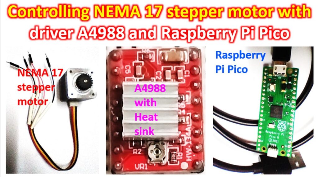
Controlling NEMA 17 stepper motor with driver A4988 and Raspberry Pi Pico
Raspberry Pi Pico is a powerful microcontroller from the Raspberry Pi Foundation. NEMA 17 stepper motor is widely used in robotics and 3D printing projects. Unlike the usual direct current motors, it moves in small steps depending on the the signals given to it. Hence it is possible to know its position without an additional sensor. A driver unit like A4988 is needed to drive the NEMA 17 stepper motor with a microcontroller. A more powerful driver is the DRV8825 driver, which I have not purchased yet.
A4988 driver has features like adjustable current limiting, protection against over current and over temperature and the facility to choose among five microstep resolutions. It can operate with a wide range of supply voltages from 8V to 35V. About 1A current can be delivered without a heat sink or forced airflow cooling. With heat sink and good cooling, A4988 driver can take up to 2A current per coil. The driver supports full, half, quarter, eighth, and sixteenth step modes of operation. Though there is a thermal shutdown circuitry, there is no reverse voltage protection for A4988 driver.
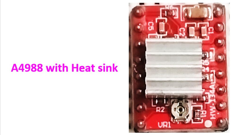
A4988 has been photographed with the heat sink so that the processor is not visible. Here is the photograph taken before the heat sink was fixed. Image has been inverted so that the processor name can be read. The preset potentiometer is seen at the top in the second image while it is at the bottom in the first image. Both these are magnified images.

VMOT pin at the top can be used to supply power for the stepper motor which may range from 8V to 35 V. Pin adjacent to that is a GND pin. Lowermost pins on the same side are the VDD which drives the internal logic circuitry running on 3V to 5V. There is a GND pin near that as well. MS1, MS2 and MS3 pins on the opposite side are the Microstep Select pins. If all the three are set at ‘low’ or zero voltage, the stepper motor works in full step mode. If all of them are set at ‘high’ then the stepper motor functions in the sixteenth step mode. Other permutations and combinations permit use in the other step modes of the stepper motor. Below that there are STEP and DIR pins. STEP controls the micro-steps of the motor while DIR controls the spinning direction of the motor. Remaining pins on that side are the ENABLE, RESET and SLEEP pins. Low input to the ENABLE pin enables the driver. Low input to the SLEEP pin puts the driver in sleep mode with minimal power consumption. Low input to the RESET pin causes it to ignore STEP inputs. It can also reset the internal translator to the initial stage of the motor. Remaining pins on the other side are the four output pins as 2B, 2A, 1B and 1A. They can be connected to any bipolar stepper motor with voltages between 8V to 35 V.

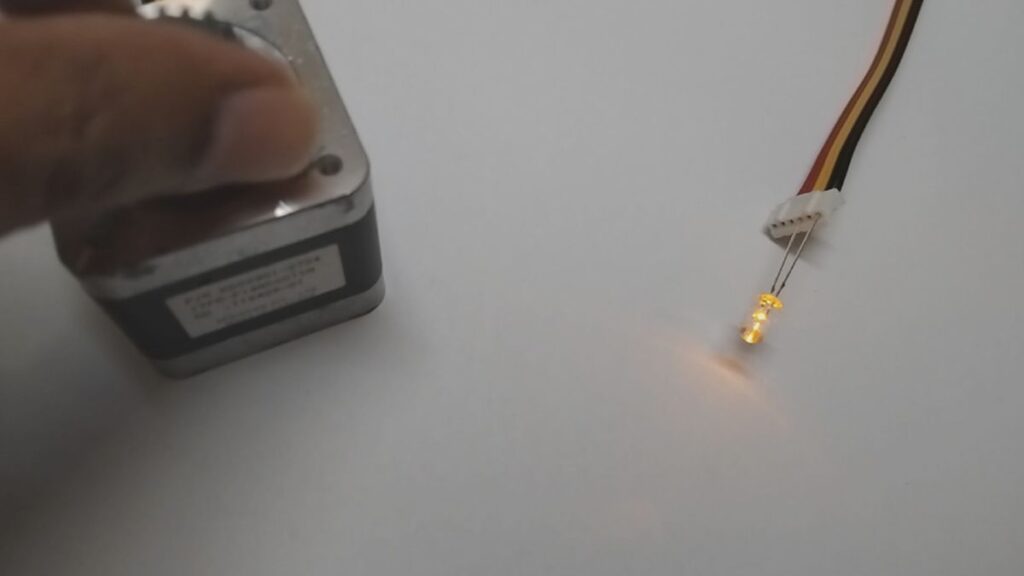
The number 17 in the name of NEMA 17 stepper motor refers to the dimensions of the faceplate, measuring 1.7 inches on each side. This motor moves in steps of 1.8 degrees, with 200 steps for a full revolution. NEMA stands for National Electrical Manufacturers Association which brought out the specifications for stepper motors. Larger stepper motors will have a larger number. Though there are six leads coming out of the NEMA 17 stepper motor from two coils, two of them are center taps and I have not connected them here.
Other than checking continuity, integrity of the coils can be checked by connecting an LED across them and rotating the shaft manually which causes the LED to light up. This particular motor has a gear fitted on the shaft.
I used the circuit diagram given at how2electronics.com. First the 2B, 2A, 1B and 1A pins of the A4988 driver were connected to the four wires from the stepper motor. They are the pins for driving the two coils in the stepper motor.

100μF decoupling capacitor was then connected across the stepper motor power supply. That was across the VMOT and GND pins of the A4988 driver.
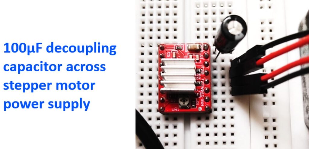
Next those two pins were connected to a 12V battery using a couple of jumper wires.

GP16 pin of Raspberry Pi Pico was connected to DIR pin of the driver and GP17 pin to STEP pin of the driver unit. They are the pins for controlling the direction of stepper motor rotation and the step.

20μF decoupling capacitor was connected across VDD and GND of the driver unit. That is the connection for the 5V power for internal logic circuitry. These were in turn connected to the VBUS and GND pins of Raspberry Pi Pico.

The 5V power was obtained by using a 7805 voltage regulator IC which would step down the 12V battery power supply.

MicroPython Code for Basic Stepper Motor Control was obtained from the how2electronics.com page and pasted into a Thonny window just as I had done for the previous blinking example LED code. Then I clicked on the ‘Run current script’ in the Run menu of Thonny and the stepper motor started moving in tiny steps! This is the first step in my future project of getting an antenna rotate according to computer code. I know it it is a long way off, but I do dream of getting my Moxon Yagi for satellite operations controlled by a stepper motor and Gpredict software in the long run.