Working of J Pole Antenna
A J-Pole antenna is an end-fed, omnidirectional half-wave (λ/2) vertical radiator matched to a 50Ω transmission line using an integrated quarter-wave (λ/4) parallel-wire matching stub. Originating from the Zeppelin (Zepp) antenna design, its J-shaped profile allows it to operate efficiently without radials or a ground plane.
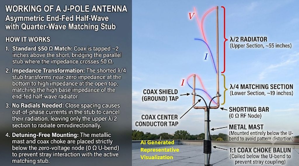
1. Structural Sections
- The λ/2 Radiator (Upper Section): The upper half-wavelength portion of the long vertical conductor does the actual radiating. Because it is fed at its lower end, it behaves as an end-fed half-wave dipole—exhibiting a voltage maximum (V), a current minimum (I), and a very high feedpoint impedance (typically 2,000–5,000Ω) at its base.
- The λ/4 Matching Stub (Lower Section): The lower quarter-wavelength parallel section—formed by the bottom segment of the main conductor and the shorter parallel stub joined by a shorting bar at the U-bend—acts purely as an impedance transformer.
2. Impedance Transformation and Feedpoint (F)
A shorted quarter-wave transmission line transforms a short circuit (0Ω, zero voltage, maximum current) at its closed bottom end into a very high impedance (maximum voltage, zero current) at its open top end:
- Top of the λ/4 Stub: Presents a high impedance that matches the high base impedance of the λ/2 radiator, allowing energy to transfer efficiently into the radiating section.
- Bottom Shorting Bar: Presents a near-zero impedance point. Because this bottom U-bend is an RF voltage node, it can be bolted directly to a conductive metal mast for mechanical support and lightning grounding without detuning the antenna.
- The 50Ω Tap Point (F): Moving upward from the shorting bar toward the open end of the stub, the impedance transitions smoothly from 0Ω to several thousand ohms. The coaxial feedline (F) is attached across the two parallel conductors—typically a few centimeters above the shorting bar—at the exact height where the ratio of voltage to current equals 50Ω (center conductor to the long radiator side, shield to the short stub side).
3. Phase Cancellation and Radiation Pattern
- Non-Radiating Stub: Because the two parallel conductors of the λ/4 stub are spaced very closely together (a small fraction of a wavelength) and carry equal currents flowing in opposite directions (180° out of phase), their electromagnetic fields cancel out in the far field.
- Omnidirectional Pattern: With stub radiation canceled, only the upper λ/2 section radiates. This produces a low-angle, omnidirectional horizontal radiation pattern identical to a vertical half-wave dipole, yielding roughly 2.15 dBi (0 dBd) of gain.
4. Common-Mode Current Control
Because a coax-fed J-Pole connects an unbalanced feedline to an inherently asymmetrical structure with no radials, RF current can spill onto the outside of the coaxial braid. Left unchecked, these common-mode currents turn the feedline into part of the antenna, skewing the vertical radiation angle and shifting the resonant frequency. Placing a 1:1 current choke (such as 4–5 turns of coax wound into an air core or several clamp-on ferrite beads) immediately below the feedpoint isolates the coax shield and preserves a clean pattern.
Compare the J-pole antenna against a Slim Jim and a 5/8-wave vertical for VHF operation:
While the J-pole and Slim Jim are both radial-free, end-fed half-wave (λ/2) antennas offering roughly unity dipole gain (0 dBd), the 5/8-wave vertical uses a longer radiating element (0.625λ) over a ground plane to compress the vertical beamwidth, delivering lower take-off angles and measurable horizon gain.
| Parameter | Standard J-Pole | Slim Jim | 5/8-Wave Vertical |
| Radiator Type | Single-conductor λ/2 | Folded-dipole λ/2 | Single 0.625λ (5λ/8) whip |
| Matching Network | Shorted λ/4 parallel stub | Shorted λ/4 parallel stub | Base loading coil (inductor) |
| Ground Plane / Radials | None required | None required | Required (3–4 λ4 radials or metal roof) |
| Real-World Gain | ~ 2.15 dBi (0 dBd) | ~ 2.15 – 2.5 dBi (~ 0 – 0.3 dBd) | ~ 3.4 – 4.2 dBi (~ 1.2 – 2.0 dBd) |
| Vertical Beamwidth | Broad (~ 78°) | Broad (~ 75°) | Compressed (~ 40° – 45°) |
| 2m Physical Height | ~ 1.5 m (3λ/4 total) | ~ 1.5 m (3λ/4 total) | ~ 1.25 m whip + ~ 0.5 m radials |
| 2:1 SWR Bandwidth | Moderate (~ 4 – 6 MHz on 2m) | Wide (~ 6 – 8 MHz on 2m) | Narrower (~ 3 – 5 MHz on 2m, coil-limited) |
| Feedline Choke Needed? | Essential (1:1 choke at feedpoint) | Essential (1:1 choke at feedpoint) | Minimal (radials decouple shield) |
Key Engineering Tradeoffs
- Gain and Take-Off Angle (The Slim Jim Myth vs. 5/8-Wave Physics): Despite persistent claims in amateur literature that the Slim Jim yields “6 dB gain over a ground plane,” NEC-4 electromagnetic modeling demonstrates that a Slim Jim has virtually the same elevation pattern and gain as a standard J-pole. Folding the λ/2 radiator alters the feedpoint impedance transformation and slightly widens SWR bandwidth, but it does not stack collinearly to compress the vertical lobe. By contrast, extending a vertical radiator to 5/8λ places a current maximum higher up the mast and concentrates radiation closer to the horizon—giving the 5/8-wave vertical a genuine 1.2 – 2 dB advantage on long-haul simplex and fringe repeater paths.
- Common-Mode Isolation and Mast Interaction: Because both the J-pole and Slim Jim lack radials, an unbalanced coaxial feedline naturally acts as the missing counterpoise unless blocked by a 1:1 current choke placed immediately below the tap point. Without a choke, RF current traveling down the outer braid distorts the elevation pattern upward, nullifying low-angle performance. A 5/8-wave vertical’s radial skirt provides a well-defined RF return path, isolating the coax shield and making tuning far less sensitive to mast height and feedline routing.
- Mechanical and Deployment Suitability:
- Choose a J-Pole for a rugged, permanent, DC-grounded copper or aluminum base antenna where protruding radials are undesirable or pose a mechanical hazard.
- Choose a Slim Jim built from 300Ω or 450Ω window/twin-lead line for an ultra-lightweight, roll-up portable antenna that covers the entire 144 –148 MHz band with low SWR and hangs easily from a tree branch or fiberglass pole.
- Choose a 5/8-Wave Vertical for mobile installations (using a vehicle roof as the ground plane) or high-elevation base stations where maximizing horizon signal strength outweighs the wind load of horizontal radials and the environmental exposure of a base matching coil.