Homebrewing UHF Yagi Part 2
Homebrewing UHF Yagi Part 2
Bought the additional items from the hardward ware shop yesterday and started working on the UHF Yagi early in the morning as today was a distraction free day at this end!
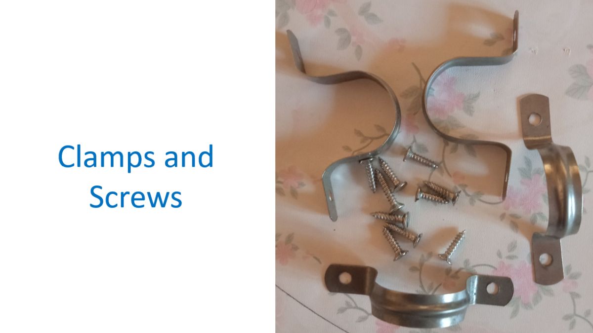
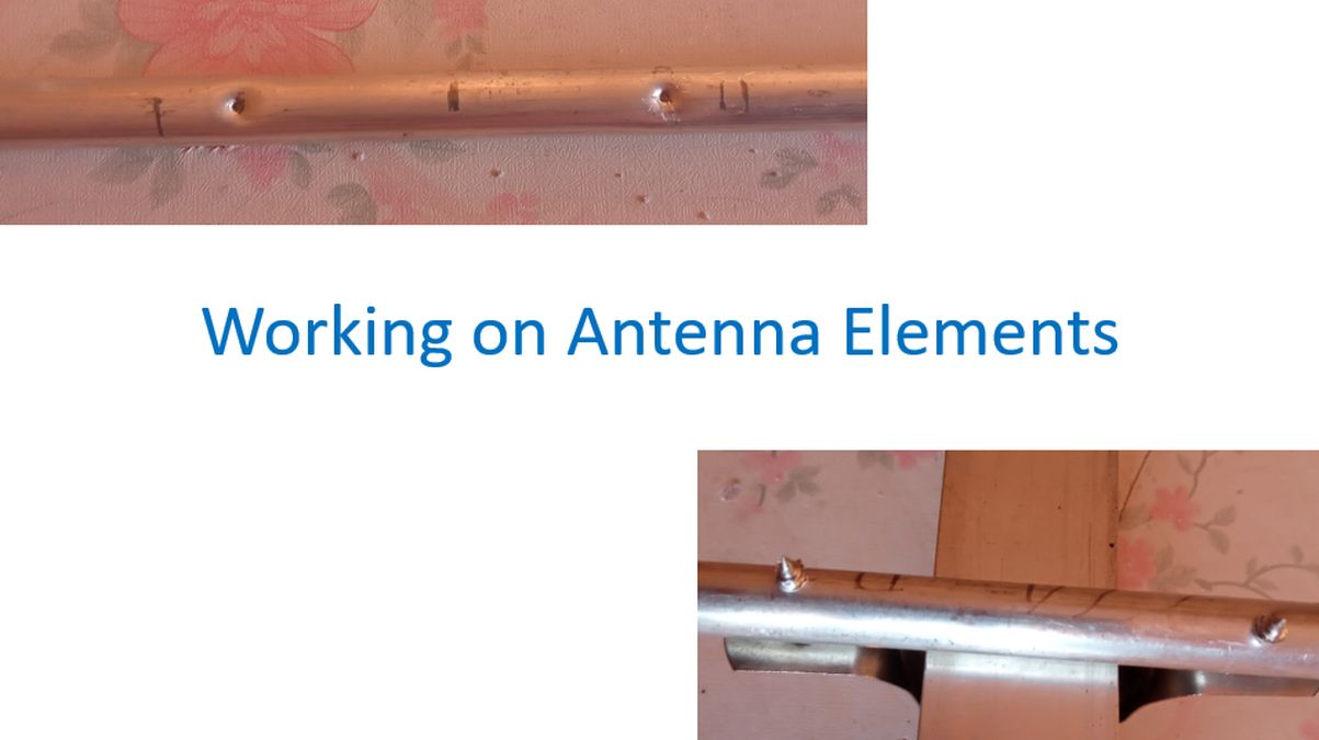
These were the clamps and screws which I could get from the local hardware shop, though not exactly as mentioned in VU2AAPs article cited earlier. Self-tapping screws were mentioned in it. But at the local hardware shop it was available from 3/4 inch size onwards only. Even this half inch screw will jut out of the 3/8 inch aluminium pipes I am using for the antenna. I had to settle with this option, with a plan to trim the remaining part of the screw later. As it was not self-tapping, I decided to drill small holes before fixing the screws.
This is the electrically driven hand drill which I had. Speed control is manual and it could be challenging sometimes. Keeping it steady was also tough and sometimes it would slip off the spot. This time I would make an intendation on the marked site by tapping an old screw in the position so that that it was easier to keep the drill steady while drilling.

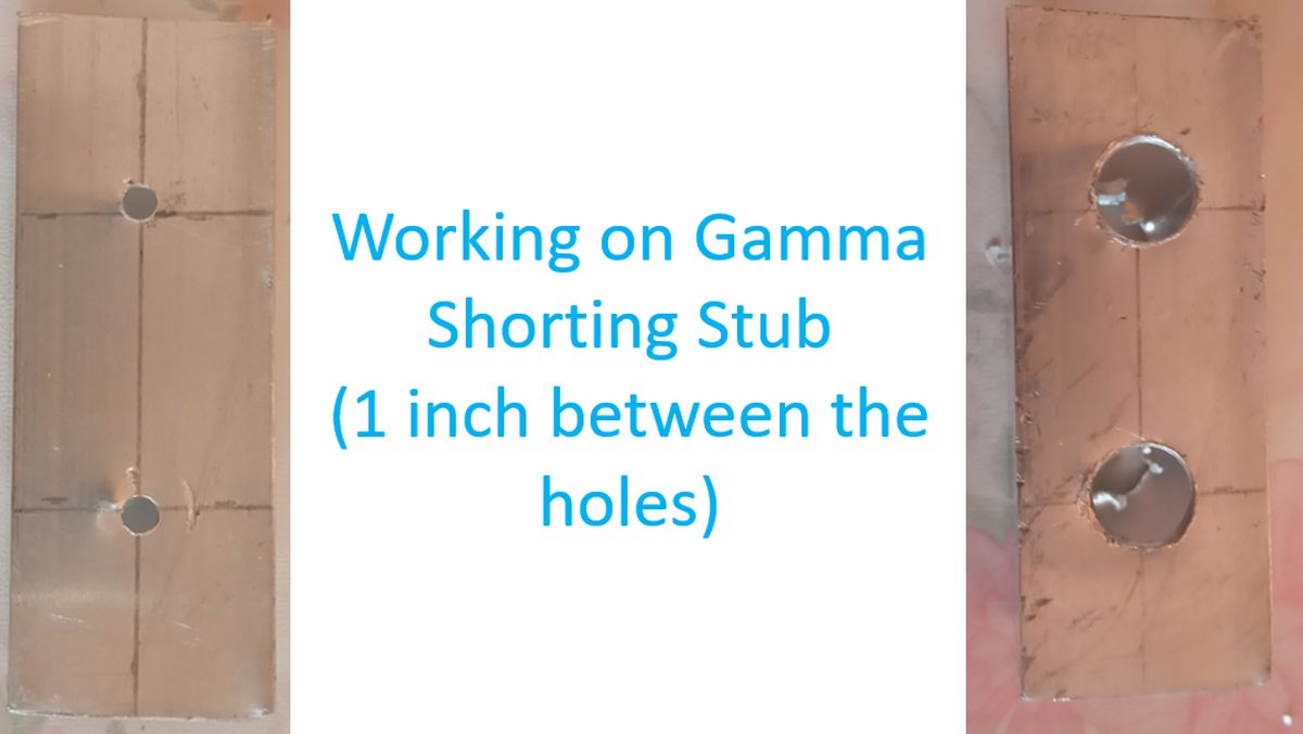
First I started working on the Gamma Shorting Stub, through which the driven element and Gamma tube for the Gamma match had to be passed. Marked a distance of one inch for the holes and punched a small hole using a smaller drill bit initially. Then serially thicker drill bits were used till 3/8 inch holes were ready for the driven element and Gamma tube. Earlier when I had tried with larger bit to begin with, while homebrewing my VHF Yagi, I found that it would keep slipping and often produced only intendations rather than drilling a hole, as it was a thin aluminium tube.
Next I started working on the antenna elements. Center point of each element was marked out. As the clamp measured 75 mm, 37.5 mm was marked on either side of the centre point. After that the clamps were placed on the marks and the position of the holes of the clamp were marked on the antenna elements on either side. After that an old screw was used to tap an intendation on the marked place. Then a hole was drilled in the position, using a drill bit smaller than the diameter of the screw so that the screw will fit tightly after fixing. Clamps were then fixed tightly to the antenna elements. As mentioned earlier, part of the screws were jutting out of the 3/8 inch aluminium tubings. The sharp tip was smoothed out a bit by using a small hammer.
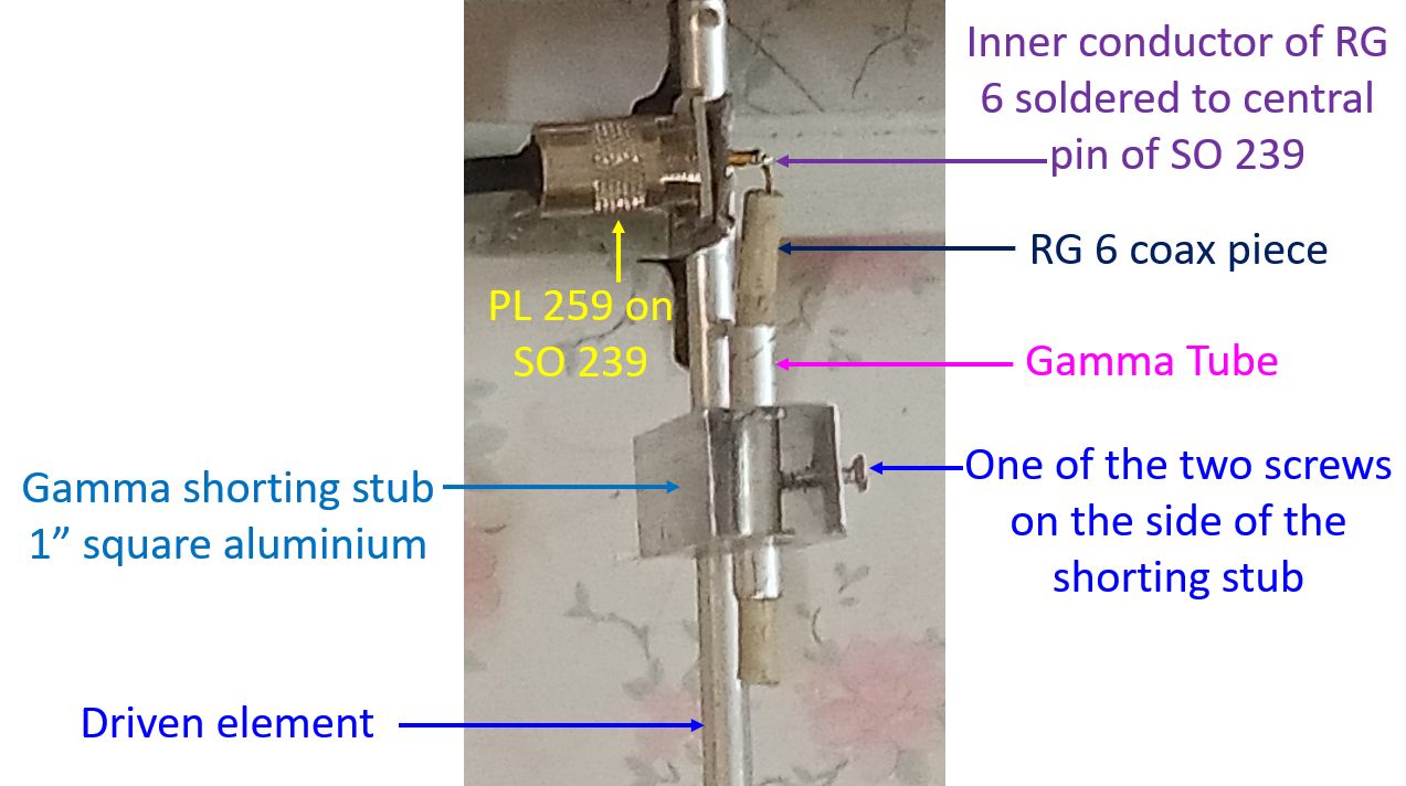
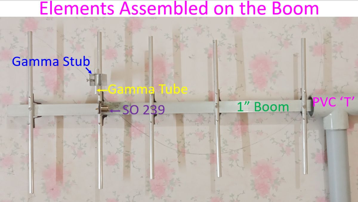
After fixing clamps to all elements, they were placed at the positions marked on the boom and one more screw fixed on the reverse side for better stability of the elements. Gamma shorting stub was passed over the driven element and Gamma tube. Two screws on the side was used to partially fix the shorting stub, but kept loose for time being to permit antenna tuning. SO 239 connector was fixed to a thin L shaped stainless steel piece and then screwed on to the boom near the driven element. PVC ‘T’ joint was placed over the boom and a one foot long PVC tube attached to it. This is to facilitate fixing the antenna on the mast and turning it in the desired way.
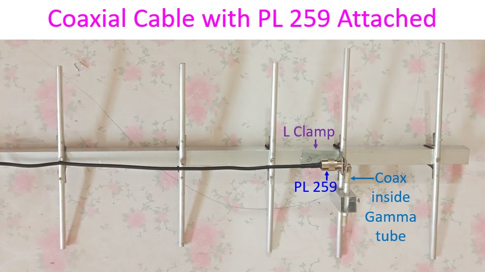
HLF 200 50 Ohms coaxial cable pre-crimped with PL 259 connectors at both ends, was obtained and on end connected to the SO 239 connector fixed on the boom. The other end will go to either the radio or SWR meter during testing. A piece of RG 6 coaxial cable of a little length more than the Gamma matching aluminium tube was taken and the inner conductor soldered to the central connection of SO 239. It was then introduced into the Gamma tube for use as a variable capacitor for tuning the Gamma match. Length of the Gamma matching tube is 5 cm for UHF Yagi. Trimming of the extra portion of the RG 6 coaxial cable and removal of outer sheath and shield are planned for the tuning stage.
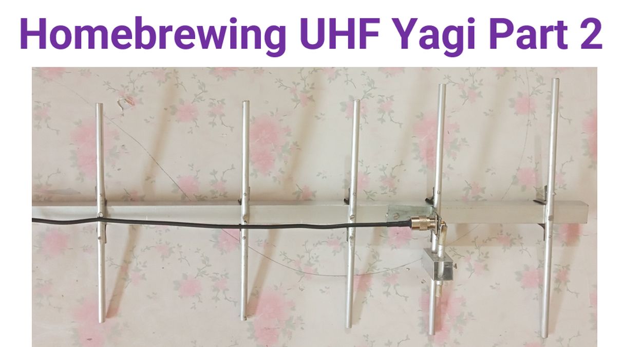
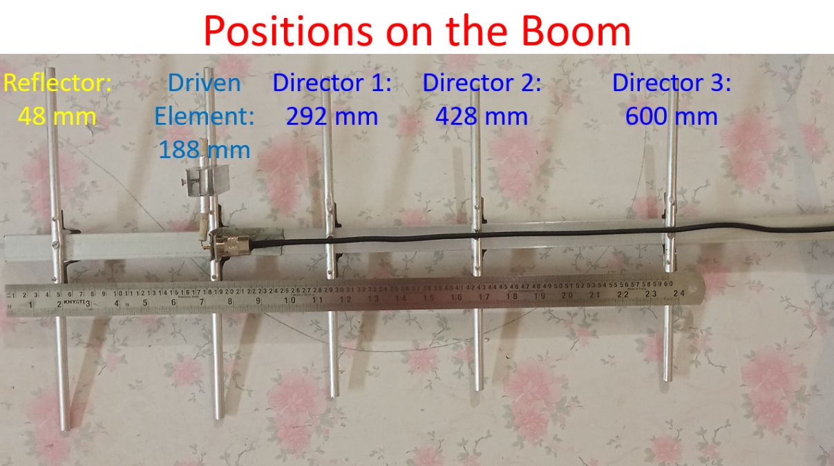
Positions of various elements on the boom can be seen in the picture. Reflector was at 48 mm, Driven element at 188 mm, Director 1 at 292 mm, Director 2 at 428 mm and Director 3 at 600 mm. As you can see, these are the approximate positions using the scale kept along with the antenna. Slight variation may be there from the original design given by VU2AAP because of technical snags while constructing the antenna without the aid of any precision instruments available at institutions. This could affect the performance of the antenna during testing.
Here is a close up of the Gamma match section. Gamma shorting stub can be slided on the driven element while tuning the antenna. Screws on its side have not been tightened fully, pending the final tuning. Inner conductor of the RG 6 coaxial cable kept inside the Gamma tube has to be soldered to the central pin of the SO 239 connector. As per the design, the outer sheath and the shield of the piece of coax has to be removed, which is being planned for the tuning stage. A short length of the coax towards the end of the driven element will also be trimmed. As the SO 239 is mounted on the boom, the outer connection will be electrically in contact with the shield of the feedline, which in turn will be connected to the ground of the radio. Inner pin of the SO 239 will receive the central conductor of the feedline. It will be coupled to the driven element through the Gamma capacitor formed by the RG 6 coax bit and the Gamma tube. The capacitance can be varied by sliding the Gamma shorting stub along with the Gamma tube over the RG 6 coax bit. After tuning, the side screws on the Gamma shorting stub will be tightened and SWR rechecked.