Dual Band Moxon Yagi – Part 3
Dual Band Moxon Yagi – Part 3
It was raining heavily here for quite a few days. So there was no chance of testing the dual band Moxon Yagi. Now it looks sunny and I brought the Moxon Yagi back to my workbench to finish the work and test it. I had finished fixing the elements on the PVC boom.
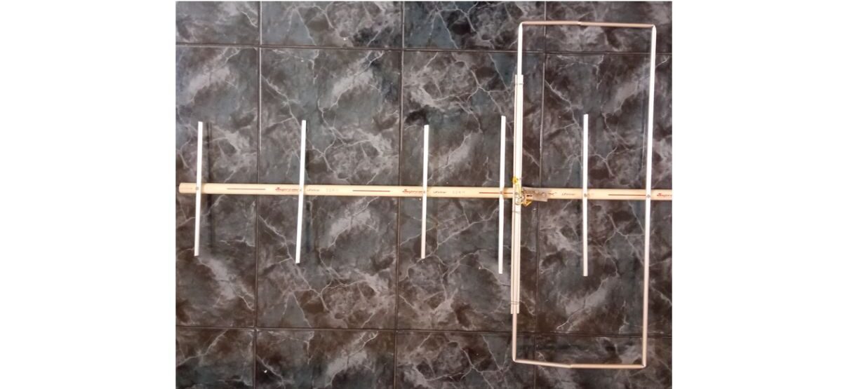
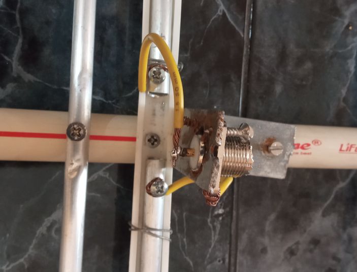
As per the design, the coaxial cable could be attached directly to the driven element. But I was not happy to cut my 10 m coaxial cable with pre-crimped PL 259 connectors at both ends. So I fixed an L shaped metallic clamp fitted with SO 239 connector on the boom. Took two pieces of insulated copper wire, removed insulation at both ends and screwed one end of each on to the driven element pieces. The other end of one of them was soldered to the inner conductor of the SO 239 connector. Second piece of copper wire was connected to the base of the SO 239.
Fiber plugs available in my store were fixed as spacers, to keep the Moxon elements in position. PVC Tee with a small piece of pipe attached to it was slided over the boom, to help in anchoring the boom on the mast, instead of using stainless steel clamps which would be costlier and heavier.
Small pieces of multiwood and other material available in the junk store were inserted between the boom and the PVC Tee to prevent it from rotating over the boom while moving. Later I can fix the arrangement with screws after the testing phase is successful. This is a temporary arrangement.
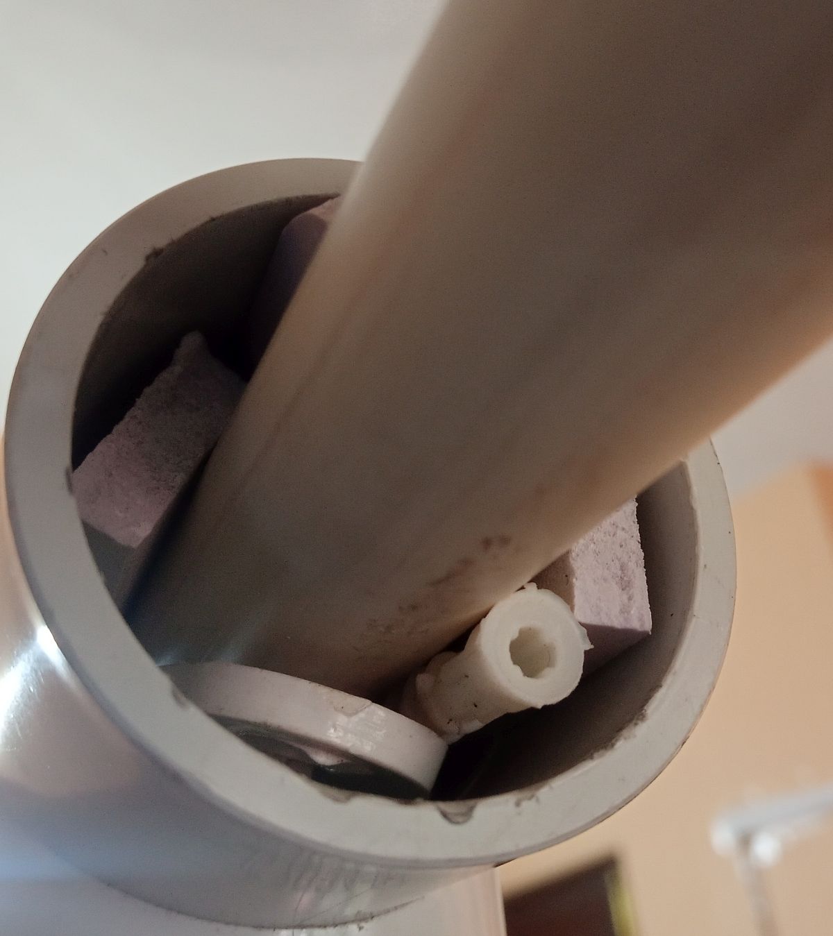
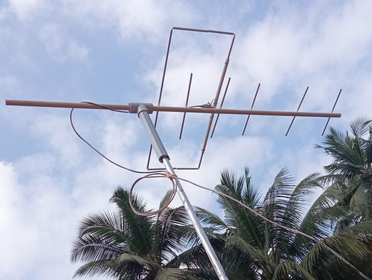
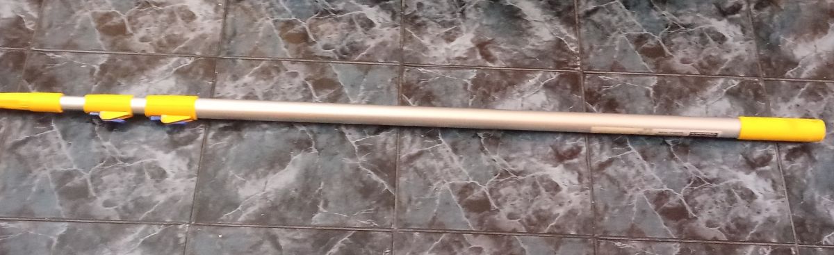
This is the two stage push up mast which was used for painting the wall at higher level. Tip of the mast was inserted into the PVC pipe attached to the PVC Tee. Small pieces of surplus multi-wood were inserted between the two, to make the joint tight.
One end of the 10 m coaxial cable with pre-crimped PL 259 was connected to the SO 239 connector fixed on the PVC boom. Incidentally I had to scrape away a bit of paint on the connector which had fallen on it while the wall was painted! There was some paint on the coax as well, which was left alone. A couple of turns of coax was wound to make an RF choke and fixed to the metallic mast. Tested the SWR on low power and found it to be 1.8:1. On UHF it is almost 2:1. Now comes the real tough part of bringing down the SWR to acceptable levels. May be I will try increasing the gap between the Moxon elements by trimming the elements a bit, on another day. Ideally I need a nano VNA to check the resonant frequency, but I do not have one!