Troubleshooting Moxon Yagi Part 1
Troubleshooting Moxon Yagi Part 1
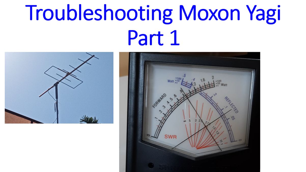
One of my friends told me that it is easy to make Yagi antenna or for that matter any antenna, but the toughest part is to optimise its performance. I have experienced this with my VHF and UHF Yagis earlier and now with the Moxon dual band Yagi meant for amateur radio satellite operations! This time I am trying to include as many video clips of the process, as requested by another friend, rather than still images. This video clip demonstrates testing of SWR using an SWR meter. As you can see, SWR is not acceptable as it is around 1.9:1. So it is certain the more work has to be done on this Moxon Yagi. Testing is being done at the lowest power of the radio, to avoid potential damage to the final power amplifier. Frequency tested for was 145.990 MHz, the uplink frequency of International Space Station.
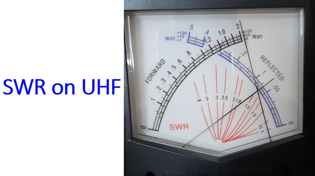
This test was for 437.800 MHz, the downlink frequency of International Space Station. Though SWR is only about 1.4:1, the forward and backward power displayed are much higher, possibly an error in the measuring device at UHF as the power output of the radio was kept at least for both tests. The needle on the left displays forward power and that on the right the reflected power. Crossing point of the two movements indicate the SWR, to be read from the red lines. Scale for forward power is marked in black and that for reflected power in blue colour. But the units for reflected power are much smaller than that for the forward power. From these readings, I felt that a lot more refinement is needed for the Moxon Yagi, to get optimal results on amateur radio satellite operations.
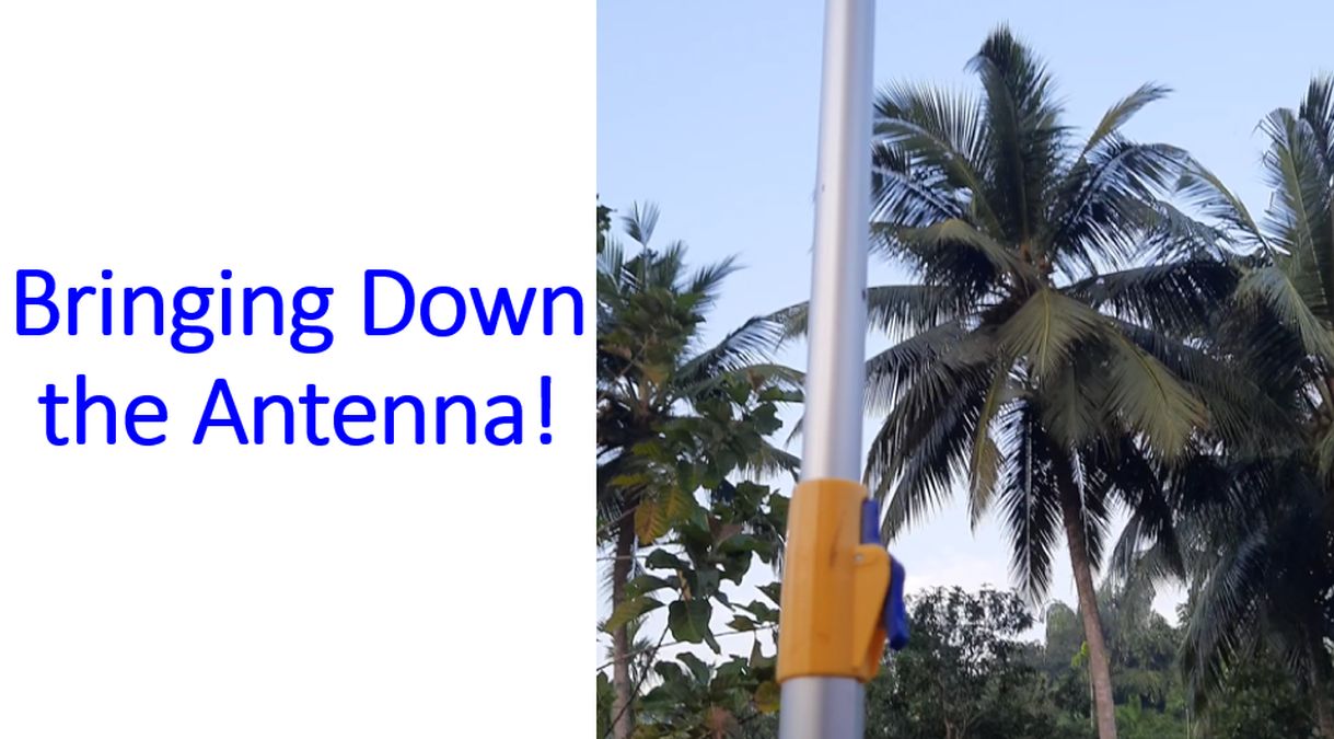
As the antenna was already mounted on the two stage push up mast, I had to bring it down for further refinements. The locking system for the push up mast can be seen as a blue latch on the orange holder. First I released the upper latch and had to give some additional pulling movements on the upper part of the mast with fingers to bring down the antenna, probably as there was some dust collected inside the system. But the descent of the lower part was very fast when I released the latch, as you can see in the last part of the video clip.
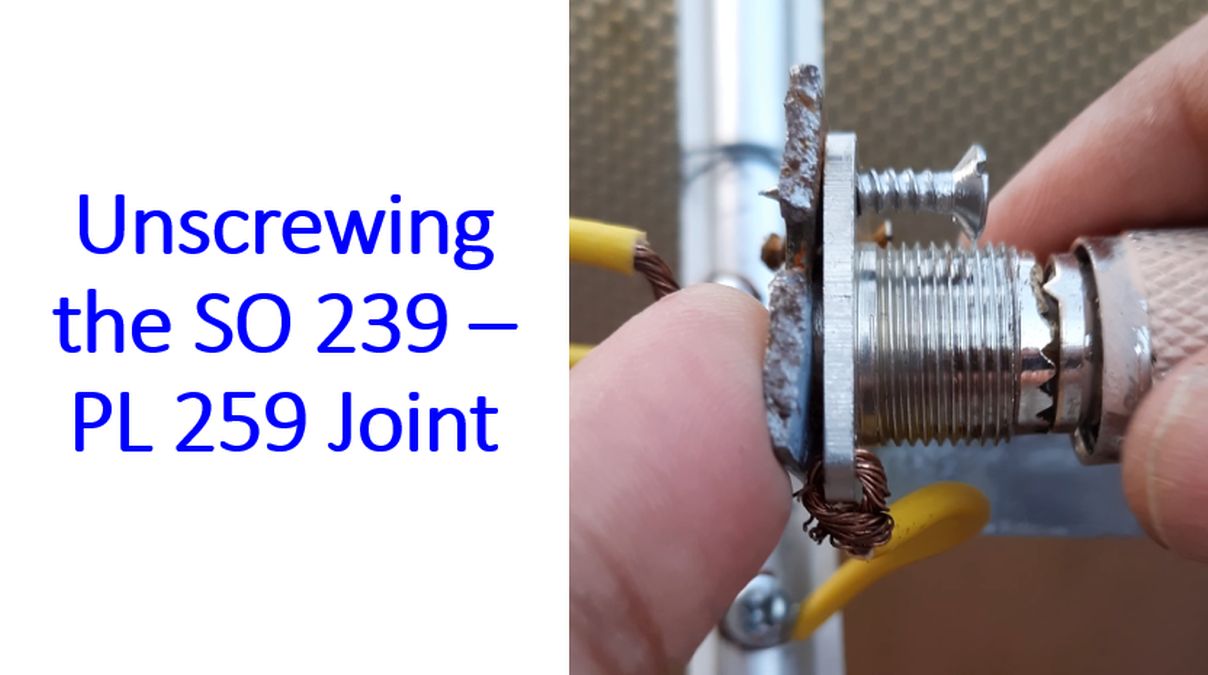
Next step was unscrewing the SO 239 – PL 259 joint to release the antenna from the cable. You can also see the imperfecton of the cut end of the L clamp holding the SO 239 connector as well as the screw that is only partially in, all part of my steep learning curve! Driven element can be seen connected to the SO 239 by copper wire, which has not been soldered together.
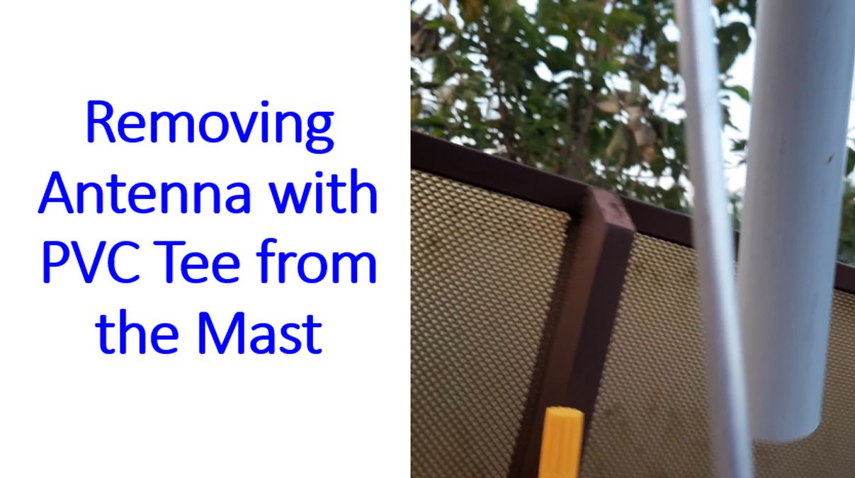
Antenna with PVC Tee attached to it was then removed from the two stage push up mast, to be taken back to the workbench for optimisation.
Once the antenna was back on the workbench, the positions of the elements were aligned so that they are parallel to each other and perpendicular to the boom. As only one screw was used to fix each element, some malalignment had occurred in the process of unmounting of the antenna.
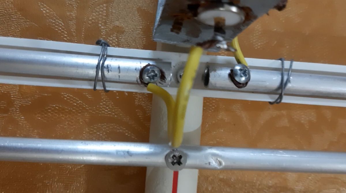
Here you can see the region where the driven element has been connected to the SO 239 connector with copper wire. One end each of the wires have been screwed to the two parts of the driven element. The other ends are connected to the inner conductor and base of SO 239.
Next you can see the spacer used to keep the driven elements in position. It is just a piece of a discarded toothbrush, carved with a knife and pushed inside the driven elements.
On the other side the spacer had become loose and fallen off, causing the ends of the elements to be malaligned.
The driven element was bent a little more to improve the alignment with Moxon reflector element.
Took another piece of discarded toothbrush to use as ‘spacer’ between the Moxon elements.
This time I used the heat of a 65 W soldering iron to shape the ends of the ‘spacer’ to fit within the 3/8 inch aluminium tubes used for the Moxon elements. You can see that I am holding the other end with a pair of pliers. Last time I had used a sharp knife to shape it and in the bargain had chipped out a part of the skin on my finger as well.
One of my friends had asked me how the aluminium pipes are bent. I had discussed it with friends. One advice was to fill it with sand, plug the ends and then bend it after heating on a gas stove. Another caution given was that sometimes you may not be able to get the sand out after bending. One of my friends told me to try bending directly and see. After all, we are not professionals looking for an aesthetic result, but happy with fair results. That is how I bent this aluminium pipe by holding it with a pair of pliers near the marked region and bending it just like that!
Next was to check the measurements of the Moxon elements after insertion of the spacer.
Simple, but not that easy step of soldering the joints of the wires on the driven elements to which it was fixed with screws. In this way I hoped to have better electrical connection. Not sure how much the looped region of wires would affect VHF/UHF transmission, with so many interactions to be thought of.
After a lot of effort the Moxon Yagi was mounted up again on the two stage push up mast, ready to communicate with Amateur Radio Low Earth Orbit satellites. This time I used tapes to hold the joints firm so that the antenna would not turn by itself in the wind. More to follow soon!