Troposcatter Propagation Model in VHF/UHF/SHF
Troposcatter Propagation Model in VHF/UHF/SHF
Tropospheric scatter is said to be the most reliable propagation mode for working DX on VHF, UHF and microwave. Other modes like duct propagation, sporadic E, auroral propagation and transequatorial propagation are less reliable than tropospheric scatter. In fact, tropospheric scatter was used widely for military communication prior to the era of satellite communication. Troposcatter is still popular among radio amateurs working at the higher end of the radiofrequency spectrum.
This enables long distance communication on those frequencies which are usually limited by line of sight propagation. It is also used in commercial communication for over the horizon communication when repeaters are not feasible. Though the two stations are not in line of sight in troposcatter propagation, the scatter volume is in line of sight for both stations. Scatter volume is a region of the troposphere which refracts higher end of the radiofrequency spectrum similar to the refraction of lower frequencies by the ionosphere.
Tropospheric scatter was discovered in 1930s and developed for over the horizon beyond line of sight communication in 1950s [1]. It was meant for use when cable links and microwave links were not feasible for communication over the horizon. But it required large parabolic reflector antennas and high power amplifiers due to large propagation loss. The expense involved was one of the reasons why it gave way to satellite communications in military and commercial communications [2].
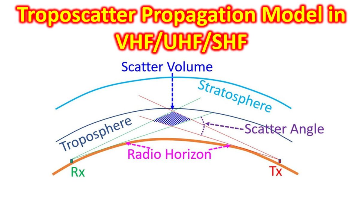
The angle between the two radio horizon rays from the communicating radios is known as the scatter angle. The volume of intersection of the two beams is known as the scatter volume. Scatter volume will be high for low gain antenna with a wider beam and lower for a high gain antenna with a narrower beam. One advantage of troposcatter over satellite communication is the lower delay. Satellite communications could have a delay of 500 ms, while troposcatter communication delays are only a few milliseconds. Another aspect is that as satellite communication cover a larger area, it can have security issues and is exposed to jamming. In this aspect, narrow beams used in troposcatter communication are less prone to jamming and security issues. Of course, it is more relevant to professional communications than amateur radio.
Development of prediction models for troposcatter propagation requires measurement of propagation losses in a long distance and over a long period of more than a year from various locations globally. There could be large range of fluctuations in troposcatter propagation depending on terrain, atmospheric conditions and weather [2].
Calculation of path loss for troposcatter includes free space path loss, scattering loss, a loss factor depending on the refractive index of air and antenna aperture to medium coupling loss. The coupling loss is a function of the scattering angle and the antenna beam widths used. Actual calculations involve complex mathematical formulae. KA1GT has a downloadable Windows program Troposcatter and Link Budget Calculator. It can estimate path loss in 50 MHz to 24 GHz region by radio line of sight or troposcatter mechanisms.
References
- Cited in: Li C et al. Cognitive Tropospheric Scatter Communication. IEEE Transactions on Vehicular Technology. 2018′ 67(2): 1482 – 1491.
- Lee et al. A Survey and analysis on a troposcatter propagation model based on ITU-R recommendations. ICT Express. 2023; 9(3):507-516.