Cubical Quad Antenna
First time I saw a cubical quad antenna was decades back, on the rooftop of a VU ham friend. It was a two element cubical quad for 20m amateur radio band. As he did not have an antenna rotator, he used to rotate it manually, which he called as ‘Armstrong method’! Yesterday, another VU ham friend has installed a multi-element cubical quad for 2m, as part of his satellite tracking system for working amateur radio satellites. Now I expect him to be heard on LEO satellites with a booming signal. Cubical quad antenna can be considered as the equivalent of two bent dipole antennas stacked one on top of another, with a single feedline. Hence they have a gain of about 2 dB over a simple half wave dipole antenna. Each limb of the cubical quad is quarter wavelength so that total length of the loop is one full wavelength.
In case of HF antennas, cubical quad antennas can be constructed over an X shaped frame with wires running around the perimeter of the square shape formed with the X frame as diagonals. Multiband cubical quads can be made with lowest band element at the perimeter and inner band elements within them, at a distance, towards the central point of the X shaped frame. This can be considered somewhat similar to the arrangement of elements in a multi-band hexbeam antenna. VHF/UHF cubical quad antennas can use frames supporting tubular elements as well. Small size will permit use of such elements without unduly increasing the weight of the antenna. Frame of a cubical quad antenna should be strong enough to resist the force of wind, which is more likely to affect the cubical quad than a Yagi antenna. This could be the reason why it is not as popular as a Yagi antenna, even though it has a gain of 2 dB over a Yagi of similar length.
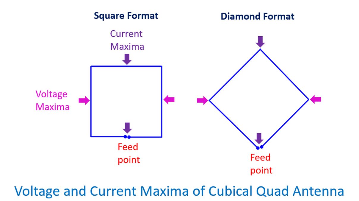
For a half wave dipole antenna, the point of maximum current is at the feed point and point of maximum RF voltage is at the ends. As a cubical quad can be considered like a couple of stacked dipoles which are bent at right angles, in opposite directions, the current maximum is at the feed point and at the point opposite to it. Voltage maxima will be at one quarter wavelength from the feedpoint. When the frame is kept like an X, the cubical quad will a have square shape. If it is kept like a ‘+’, the shape of the cubical quad can be considered to be diamond shaped, there being 45 degree tilt in the frame between these two orientations. Both these formats in the usual type of mouting give horizontally polarized signals. If the antenna is rotated ninety degrees, it can radiate vertically polarized signals, as in case of Yagi antennas.
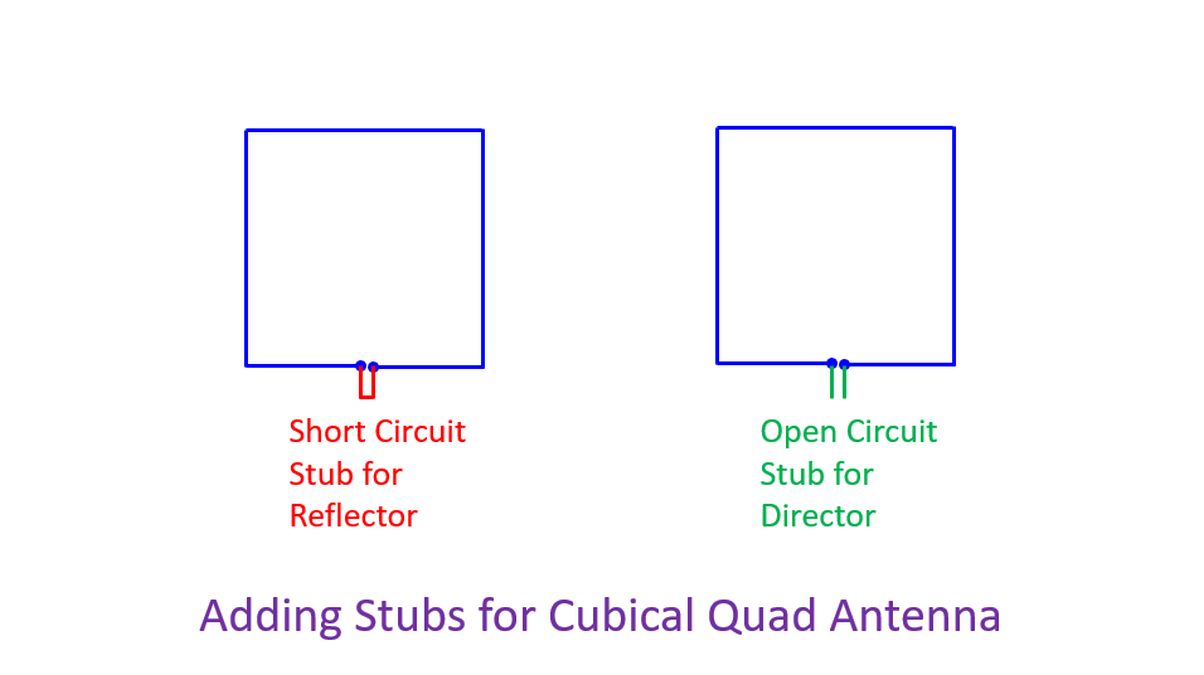
As with Yagi antenna, cubical quad elements can be arranged on a boom with one reflector behind the driven element and a series of directors in front to create a beam antenna. A reflector behind the driven element which is slightly longer than the electrical full wavelength by 3-5% will make it inductive and resonate below the nominal frequency of the driven element. Another way is to use the same length reflector element and add a small short circuit stub, offering some mechanical advantages for the quad beam antennna. Directors should have either shorter length or a an open circuit stub so that resonance is above the nominal frequency and be capacitive. Adding more directors will increase gain in a decremental way. 0.15 to 0.2 wavelength spacing between the elements will give a feedpoint impedance around 50 Ohms. While reflector gives a gain of around 5 dB, first director gives an additional gain of 2 dB. More directors increase gain by 1 dB each. Four or five directors will be optimum in view of diminishing returns with large number of directors.