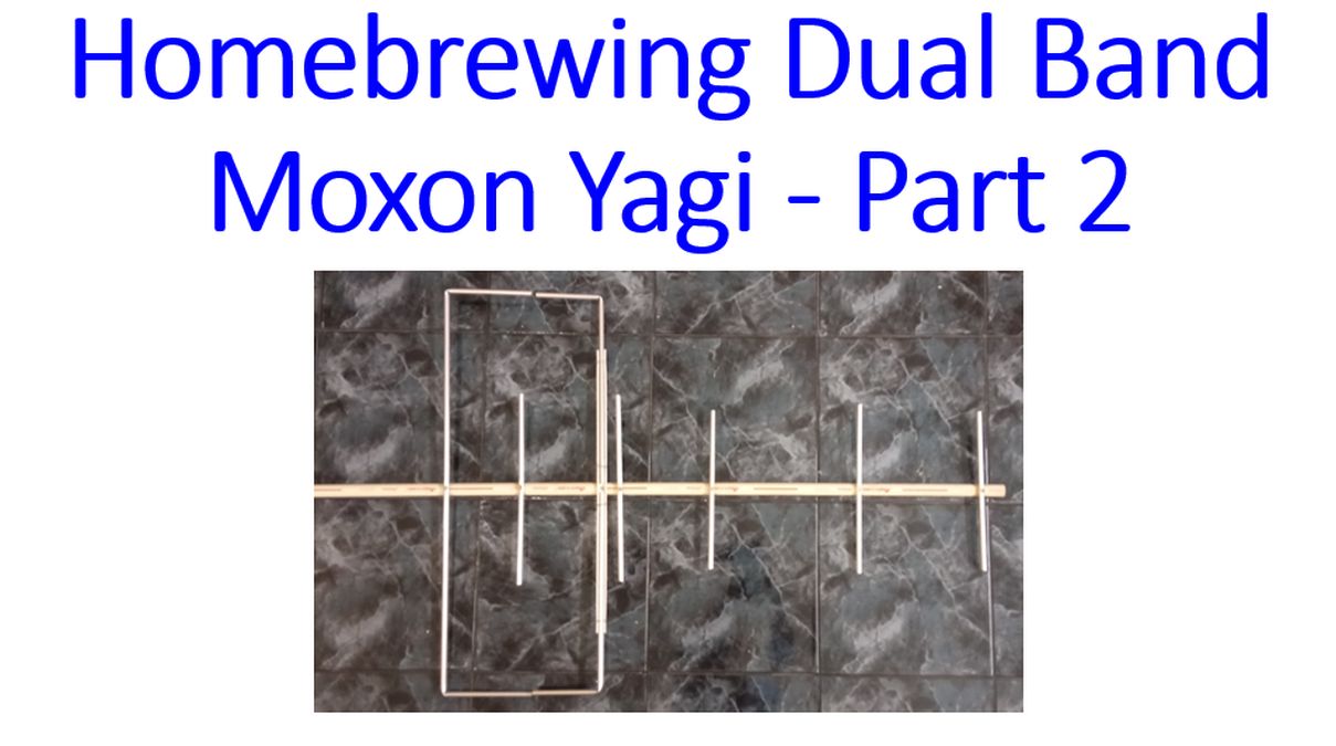
Homebrewing Dual Band Moxon Yagi – Part 2
Homebrewing Dual Band Moxon Yagi – Part 2
Came back to work on dual band Moxon Yagi. I had finished cutting the 3/8 inch aluminium pipes and shaping the VHF Moxon part. Next step was to mount it on the boom. As a wooden boom as mentioned in the design was not there in my store, I took a surplus piece of PVC pipe, about 3/4 inch in diameter.
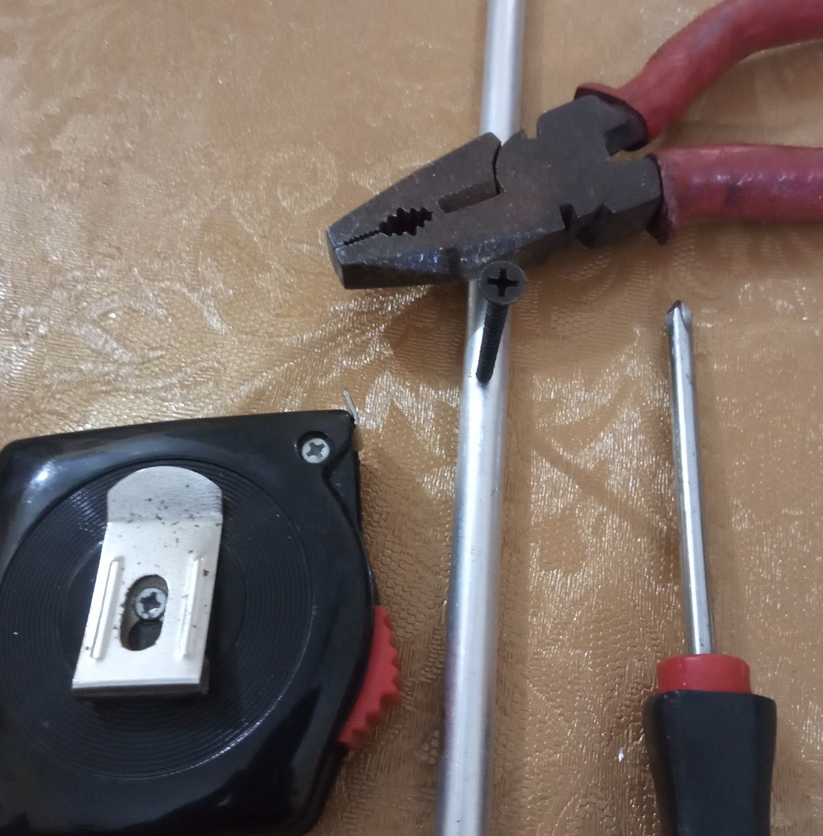
These are the tools which I was using: Pliers, star edged screw driver, steel measuring tape and an additional long, sharp screw for marking. First I marked the mid point of the aluminium tube antenna elements for fixing the screws. Then I used the pliers to hammer the screw a little bit to produce a dent in the aluminium tubing so that the drill bit would not slip away while I try to drill it. Then I would drill a hole a bit smaller than the size of the screw to be used.
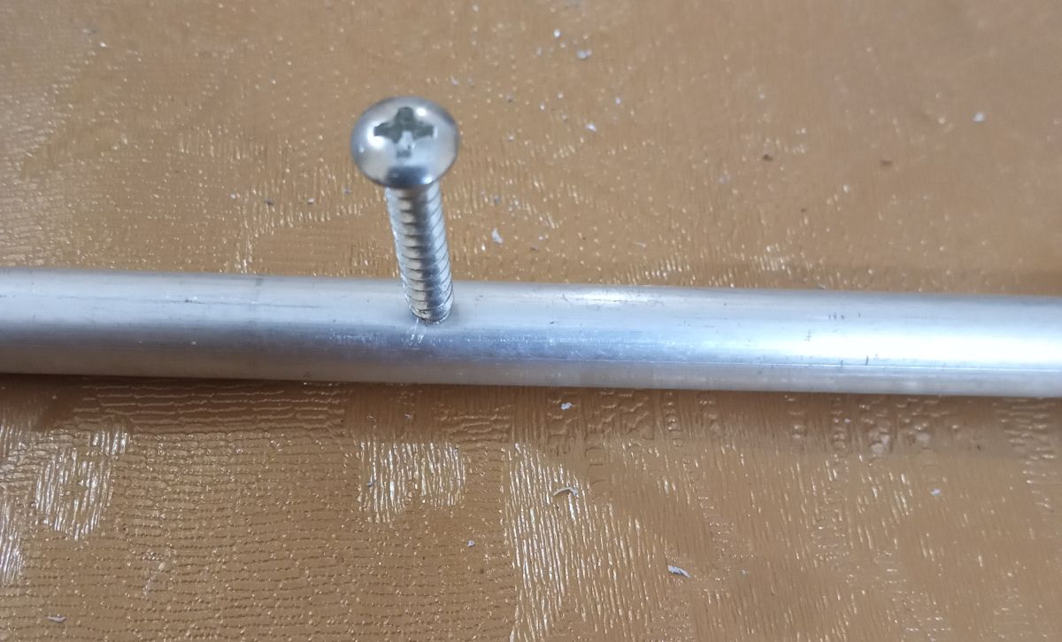
The final screw to be used was then threaded into the hole and taken out, to make it a bit easy to fix on the boom. Elements were fixed one by one on the PVC boom, by fixing the screw in the centre, on the position marked on the boom as per the design.
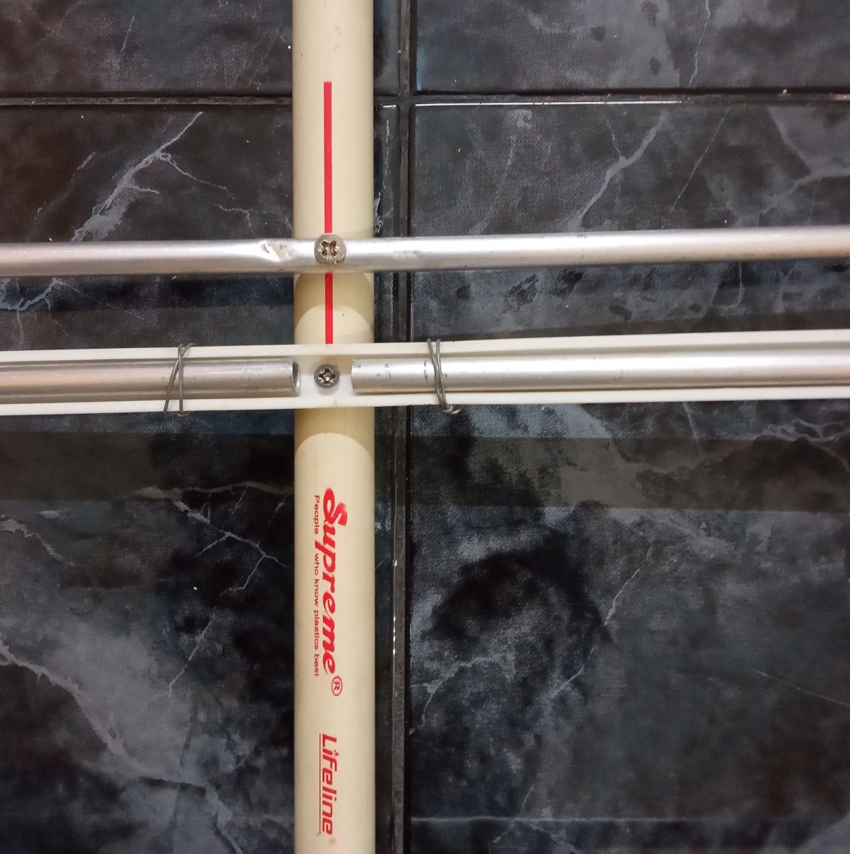
As the driven element of the VHF Moxon had to be in two pieces, it could not be fixed on the boom with a screw. So I fixed a length of surplus piece of PVC channel used for electrical wiring in the position for the driven element. The two pieces of the driven element were placed inside it and tied with GI winding wire at both ends. Picture shows the central part of the cut driven element and the adjacent UHF element. As mentioned earlier, it is a passive coupling between the VHF driven element and the UHF element so that only one coax is needed as the feeder. No diplexer is needed either. Forward gain is mentioned as 3.95 dBd on VHF and 8.06 dBd on UHF. As discussed earlier, dBd is gain in comparison with a dipole antenna.
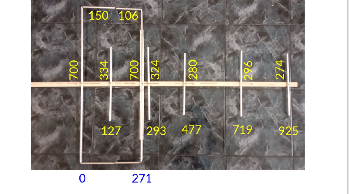
Positions of the elements on the boom and the dimensions as per the M1GEO/G8OCV design have been marked in this picture. You can see that one UHF element is within the Moxon and another one is very close to the driven element. Fourth UHF element is seen to be longer than the third. I presume that it is not an error as they have arrived at the design after simulation and testing. The coaxial cable has to be connected at the centre of the driven element. All measurements are in millimeters and the position of the driven element is at 271 mm. Total length of the antenna is less than one meter and it is quite light so that it can be used as a hand held antenna. A little extra length of boom before the driven element can be used as a hand grip or a custom made grip can be added later. Next phase will be fixing the coax, mounting and testing the antenna.