Importance of a Good Ground Plane for Magnetic Mount VHF Antenna
Importance of a Good Ground Plane for Magnetic Mount VHF Antenna
Hello friends, today we are going to discuss the importance of providing a good ground plane for magnetic mount VHF antenna.

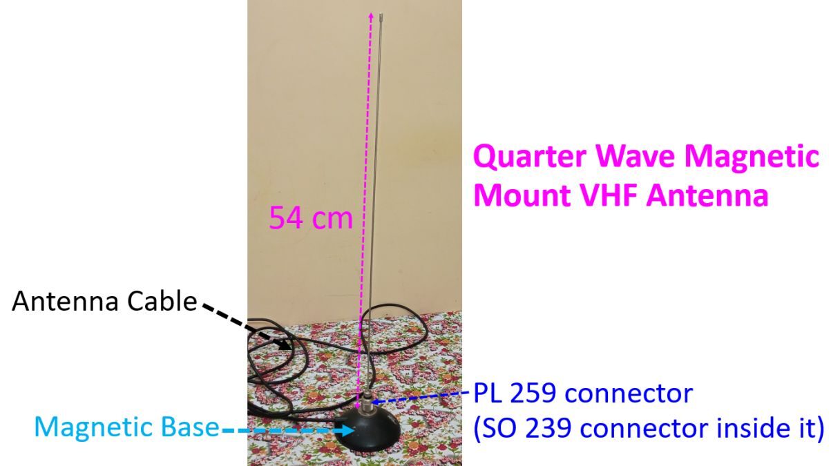
I am going to describe my experiments with my Magnetic Mount VHF qaurter wave antenna which measures 54 cm from lower end of the PL 259 connector to the tip of the antenna. Magnetic base is below the PL 259 connector which is attached to an SO 239 connector attached to the top of the magnetic base. This magnetic mount antenna is meant for use over the metal body of a vehicle, which will provide a ground plane. My experiment is for using it in other situations at home, as an internal antenna to access nearby VHF repeaters when an external antenna cannot be used as during raining season when lightning can occur unexpectedly. I had used it earlier, mounted on a window grill and multi gym. But at that time I did not have an SWR meter! That was before I purchased my external CP22E 5/8 wavelength vertical and SWR cum power meter.
I am using my old TM 261 VHF base station on low power for these tests. VHF base station has been connected to a small 12 volts 1.3 AH sealed, rechargeable lead acid battery. It is meant only for tests as the capacity is very low for regular operation. But its size is very small so that it is very easy to carry arround for tests! The VHF base station has been kept on a blue coloured power bank just to give an inclination to make the screen visible to me more easily.

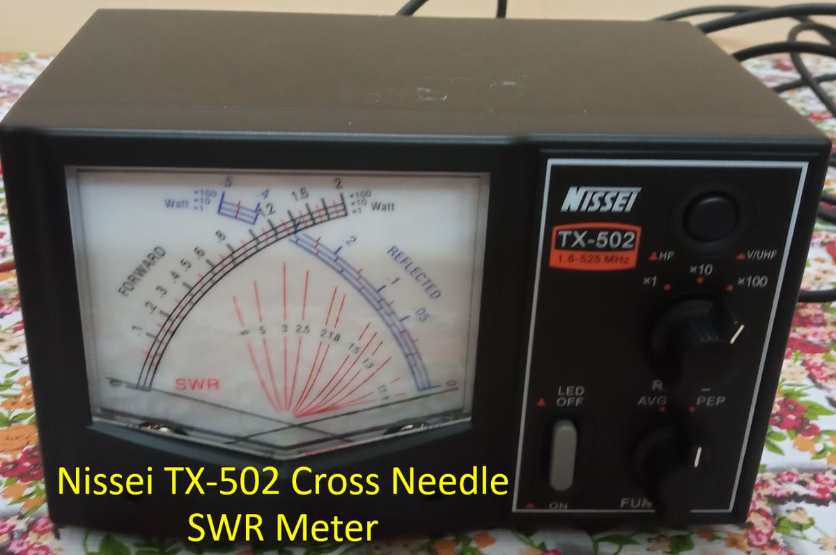
I am using a Nissei TX-502 Cross Needle SWR Meter for the tests. It has an operating range from 1.6 to 525 MHz. Push button at the top right corner is used to select between HF and VHF/UHF ranges. If the button is pushed in, it selcts VHF/UHF range, which I am going to use for the current experiments. Rotary switch can be used to select the power range from x1, x10 and x100. For experiments at low power using the VHF base station I will use x10 setting as the lowest power in VHF base station would be around 5 Watts. Forward power is shown in the black scale and reflected power in the blue scale. The point where the two movements cross will show the SWR on the red scale.
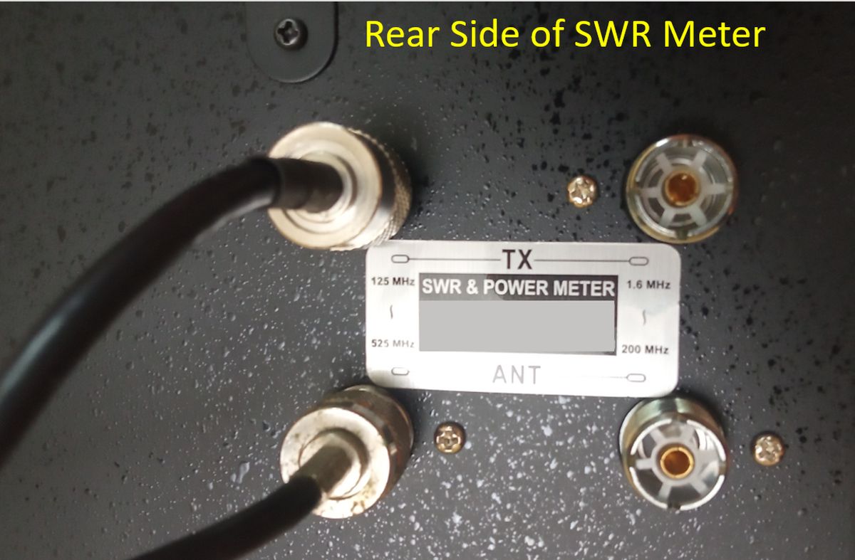
Rear side of the SWR meter has four SO 239 sockets. One set is for the frequency range from 125 MHz to 525 MHz. Second set is for 1.6 MHz to 200 MHz. Though both sets can be used for VHF range, I am using the first set. Upper socket is connected to the radio while the lower socket is connected to the antenna. A patch cable with PL 259 connectors at both ends is needed to connect the SWR meter between the radio and antenna cable as the radio has an SO 239 ouput connector and SWR meter has SO 239 for input and output. Antenna cable has a PL 259 connector at its end.
First I checked SWR with the base of the magnetic mount kept on the wooden table, just for information. As expected, the SWR was high, nearly 5:1. Anything above 2:1 is not acceptable for regular operations, as it will damage the final stages of the radio. Sometimes the cable also will heat up and get damaged, if higher powers are used. Tests are only for a few seconds and I hope that it will not cause permanant damage to my equipment. Note that the forward power is shown as about 3.5 Watts and reflected power about 1.5 Watts.

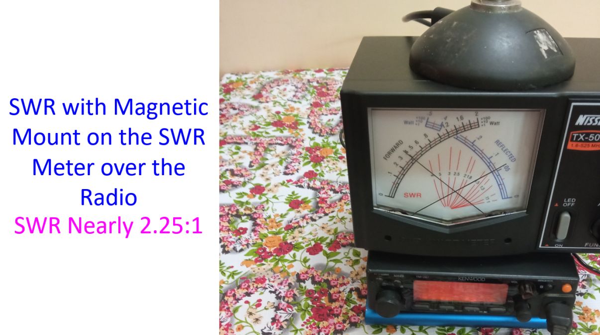
After that I tried keeping the magnetic mount on the SWR meter which was kept over the radio, for convenience of getting a photograph of all in one frame. That gave an SWR of almost 2.25:1, which was much better, because the metallic body of the SWR meter would provide a fair ground plane for the Magnetic Mount VHF antenna, though not enough as can be seen from the still not ideal SWR. Note that the forward power has increased to nearly 4 Watts and reflected power is about 0.6 Watts only. You can understand the importance of providing a metallic ground plane, though not an ideal one.
As the next step in the current series of experiments, I placed the Magnetic Mount VHF antenna on a steel table, in the next room. Now you can see that the forward power is almost full 5 Watts and the reflected power movement is hardly above the baseline. SWR is near ideal, almost 1:1! In this position, I could access Calicut repeater, which is less than 4 km from my location. I could not attempt any contact because it was too early in the morning when I conducted these tests. All these tests were conducted with the antenna in vertical position, meaning that the electromagnetic waves would have vertical polarization, suitable for terrestrial communication.

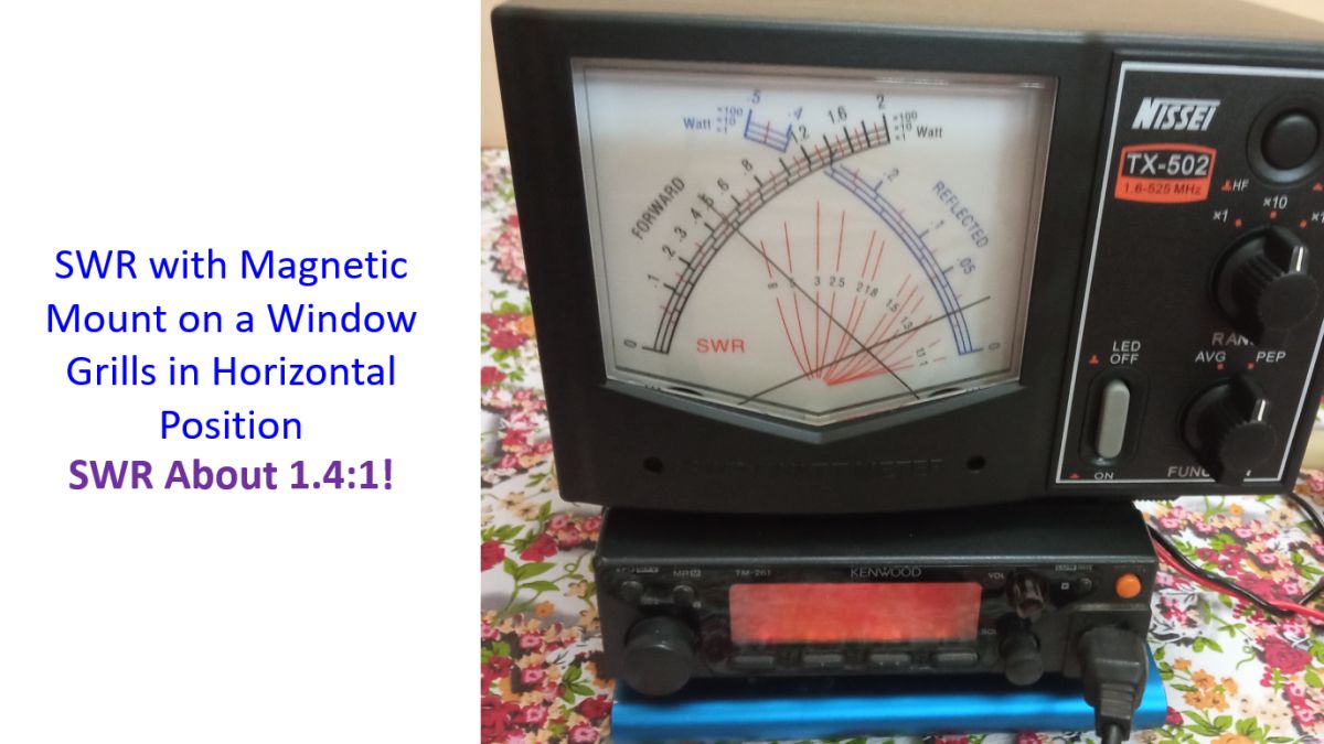
Next was to try the magnetic mount on the window grill. Earlier I had used it on the window grill for acessing the local repeaters from the first floor with the antenna kept vertical. This time I tried the antenna in the horizontal position on the upper part of the metallic window grill, just for checking the SWR in that position. That position would not be ideal for accessing local repeaters as the electromagnetic waves will be horizontally polarized and the repeater antenna would be vertically polarized, being an omnidirectional vertical antenna for reception from all around. SWR with magnetic mount antenna on the window grill in horizontal position was 1.4:1. I did not expect any access to the local repeaters in that position and did not find it. But by that time the production charge in my new battery had drained off and I had forgotten to buy a charger! So I had to stop my experiments for time being. I expect the next SWR measurements will be with my seven element VHF Yagi, which has been partially homebrewed and is awaiting completion.