Moxon VHF/UHF Yagi for LEO Satellite Operations
Moxon VHF/UHF Yagi for LEO Satellite Operations
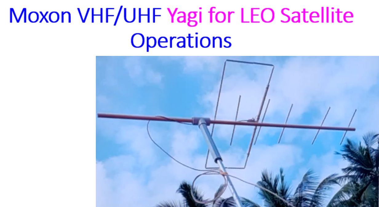
Here is the transcript of the video on Moxon VHF/UHF Yagi for LEO Satellite Operations: Today I am demonstrating my Moxon Yagi for LEO satellite operations. This has been mounted on a push up mast, in a fixed elevation and azimuth. That is because I do not have an antenna rotator, and I am also not able to work outside the home because of local restrictions. Ideally, this should be used as a hand held antenna, or placed on a tripod, outside your home, and operated in such a way that, the antenna can be rotated in the axis, as well as in the direction of the satellite, in azimuth and elevation. Rotation in the axis is meant for adjusting polarization. We know that satellite in orbit is not just moving around, it tumbles and there are changes in the direction of the satellite antenna, which is occurring continuously, so that, a particular polarization, this is a linear polarized antenna. It can be kept either horizontally or vertically, but that will be linear polarized. So when it is a linear polarized antenna, and the satellite antenna is changing direction, they will not match fully well. That is why advanced operators use cross Yagi, with two elements in a cross and there will be multiple such cross elements which will produce circular polarization. But this is a very limited setup. This produces only linear polarization. So when you are operating outdoors, you can rotate it in such a way that it can match the polarization of the antenna. But this is not that way, this is a fixed position. You can see that, the larger element in the shape of a rectangle, is the Moxon rectangle, or Moxon element, which has been used for VHF. This is a VHF element, that is why it is larger and you have five UHF elements over here. All these have been mounted on a PVC pipe, which is surplus from wiring, that is electrical wiring pipe, it is being used here. This is a PVC Tee which has been used, and a length of PVC pipe, for mounting it on the push up mast. An coax has been made into a couple of circles over, that is acting as an RF choke, or line isolator. Of course, this is not a very ideal type of construction, this is only a prototype and I am also learning the process of making antennas. This is in fact my third antenna, but of the lot one of the most successful. Advantage is that, it has only one feedpoint. Usually, VHF/UHF antennas have two feedpoints. There will be two cables coming out of it. Here, the Moxon element is passively coupled to the UHF elements. So there is no connection to the radio for these UHF elements. So there is only one feedline.
As there is only one driven element, and only one feedline, you do not need a diplexer, the circuit to isolate between the two is not needed, that is the advantage. And when this boom is made by PVC, and these are made by aluminium pipes, 3/8 inch aluminium pipes, the Yagi itself is very light for outdoor operations, but I am not using it for outdoor operations. I have connected this to the radio in my shack and that is a limited way of operating satellites as you will not be able to rotate it without a rotator and we will not be able to twist it in the direction of polarization and this is only a linear polarized antenna. Still, with this antenna, I was able to work International Space Station voice transponder, several times, Tevel satellites, and recently AO 91 satellite, and more important, I was able to receive Slow Scan Television Images, SSTV images, during the great SSTV event from International Space Station in the past few days. Several images could be received, with this very limited setup.
A little bit about the principle of Moxon rectangle, named after les Moxon. This is the driven element, which is cut into two, and this is the Moxon reflector element, both together form a rectangle. Reflector element is longer, and insulators are in place to keep it fixed in a rectangular position, in a single plane. This is the feedpoint. And the advantage of this Moxon position, is that if you lengthen these to either sides, then the horizontal dimension of the antenna increases. This is a simpler way to make the antenna horizontally shorter in dimension, without losing its effectiveness. This has a directivity in the direction of the feedpoint and it has modest gain and a high front to back ratio. That is the advantage of the Moxon rectangle. There is a software known as MoxGen by AC6LA, which can be used to calculate the dimensions of the Moxon rectangle, for a given frequency of operation. That software is available online. You can use that to calculate the dimensions, which ever part you want to know. I have not calculated personally, I made the Yagi by a design available online, which has been tested and proved, and it has been used by very many LEO satellite operators worldwide.
This is the picture taken soon after I had cut the elements for the Moxon Yagi. This is the Moxon section and this is the Yagi section. That is just like the Yagi-Uda antenna. Only difference is that, this Yagi section will not have any direct connection to the radio, it is passively coupling to the driven element of the Moxon rectangle. Only difference is that, and in the design which was given online, they were using aluminium welding rods, of 3.2 mm diameter. I had these pipes, these are 3/8 inch aluminium pipes, which I had bought for making my conventional VHF and UHF Yagis. So I had plenty of this in surplus. So I did not want to get an additional 3.2 mm welding rods. Of course, that was also not available in any of the local markets. I have to buy it online from somewhere else. The problem here was to bend the pipes. I discussed with several persons. Some said that you can fill sand within the pipe, plug at both ends and keep it on a gas stove and bend it here, and somebody said that, after bending, it may not be possible to take out the sand also. Another person, one of my friends, told to me, why should you bother so much, just bend it like that, using a pliers. That is what I have done and you can see that the ends are not very neat. Still it works, that is the more important for amateur radio. We are not professionals and we want our setup to work, rather than have an aesthetic importance. So I didn’t make much time making this section, because it was very easy, keeping a plier here and then bending it just like that, without using any filling of sand, keeping on gas stove, all having their own risks. I just bent it like that, even though that is not aesthetically nice. And this is I have just kept it on the floor and taken a photograph, to show the VHF and UHF elements.
These are the dimensions as per M1GEO/G8OCV design. This is I think a father and son duo. They have used vector analyzers and perfected their design from another design. And this is not exactly their design, as I have made some modifications, to suit my local situation. These elements, instead of the 3.2 mm aluminium rods, welding rods, which they have described, I have replaced it with aluminium pipes, 3/8 inch aluminium pipes, which are available locally and quite cheap also. And the boom they have described is a wooden boom, which again, I did not go for that, because I didn’t have it. This is a circular pipe, that is a PVC pipe, surplus from my home wiring programs. Then another difference was, they had soldered the connections, coax connections to the driven element directly, at this point, feedpoint. As I did not want to do that, as I had a short length, 10 meter cable, or coaxial cable, HLF 200 coaxial cable, with PL 259 connectors at both ends. So I didn’t want to cut it and get it raw. I fixed a SO 239 connector, on the boom, using an L clamp, which I had been using for my other antenna projects, and I used short pieces of insulated copper wire, to connect to both feedpoints. I can show you a picture of that soon. And these are the dimensions. These dimensions are positions on the boom. This is the position of the Moxon reflector element, this is the position of the Moxon driven element, and given in yellow are the positions of the UHF elements, on the boom, this as zero. And what is given vertically, are the measurements of the elements. This seven hundred means, this dimension. And this portion is 150 mm. This portion is 106 mm. These two portions are same, 700 each and you can see the measurements of each of the UHF Yagi elements, a difference is seen here. I would have expected this should be shorter than this one. But there is a difference in the distance also, it is not uniform. Whatever, it was by modeling by M1GEO and G8OCV. I didn’t want to change it because, I don’t have any modeling software, nor do I have a vector network analyzer. I only have a SWR meter. So I didn’t want to change it. It was just a trial and error. Final stages I had to trim these driven element a little, mainly because this was very near each other. Now I had to trim a little bit, and I fixed the spacer here also. So I have made some modifications and various testing. Initial SWR was 2.5:1, and finally I have been able to bring it down to about 1.4, 1.5 both for VHF and UHF elements. They had found that this has better performance on UHF than VHF. I have been able to use this antenna both for V/U satellites which are more common in this region, and U/V satellites. U/V satellite means uplink on UHF and downlink on VHF. Both types of satellites, I have used this antenna, with fair success.
This is the way I connected the SO 239 connector to the driven element with two pieces of insulated copper wire. I had soldered here initially only, then later I had soldered this joint, this joint as well as this joint during my revisions and the gap was also adjusted later, to be uniform, all during the testing process, as I found the SWR was 2.5:1 initially and the performance was not good. So I brought the antenna down several times and adjusted each parameters. I had to change the dimensions, I mean not the dimensions. This was poor workmanship, I had kept it not very accurately and that I had adjusted later. This of course I could not do it because this is, I found it very tough to cut this piece of clamp, which was made of galvanized iron, I think. It was not being cut well with my Hacksaw blade. So really tought time. Drilling the hole for the SO 239 was also difficult, I had drilled many holes initially and tried to coalse them, finally it didn’t work. I took to the industrial and got their flak as well for trying such crude methods! Anyway, finally I could get an SWR of nearly 1.5:1 and I could get the antenna working.