Practical Implementation of Gamma Match
Practical Implementation of Gamma Match
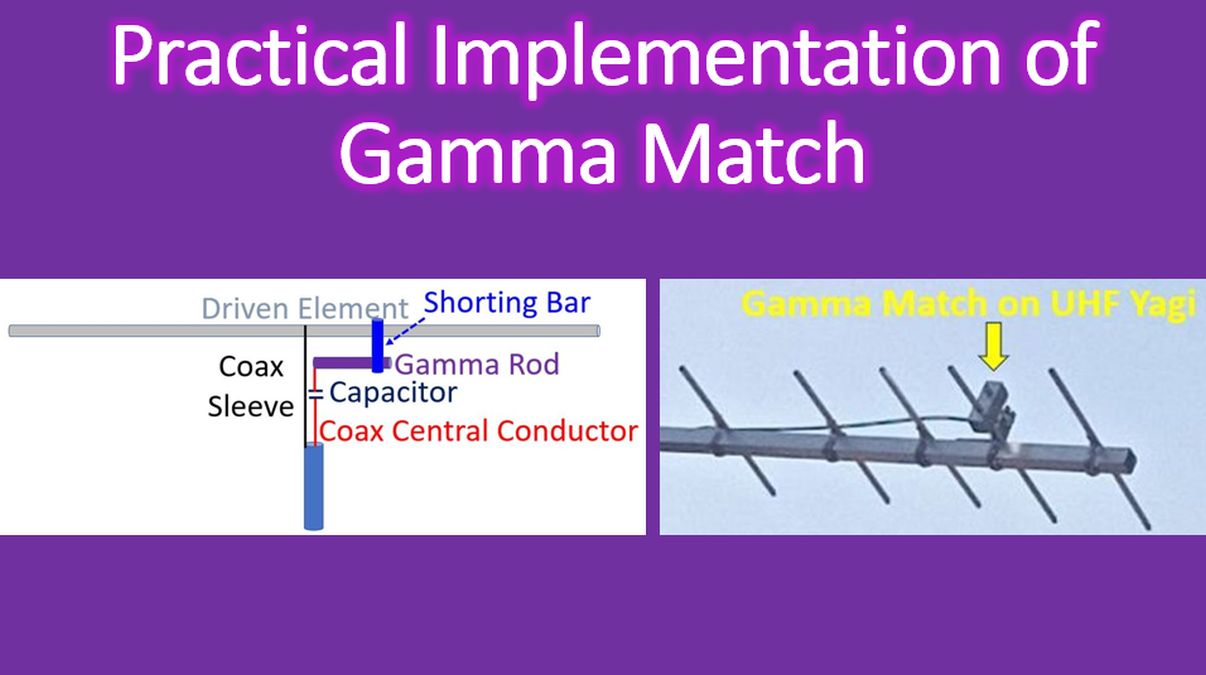
Here is the transcript of the video: Gamma match is an arrangement used to match the impedance in both HF, VHF and UHF antennas, typically for Yagi-Uda type of antennas. This is the driven element. The advantage while using the gamma match is that, the driven element need not be cut into two. The central voltage here, RF voltage is zero. So the outer sleeve of the coax can be connected directly. Similarly, this driven element can also be mounted one a metallic boom, with this center point, as the RF voltage is zero there. So there is no need for insulation of the driven element from the boom, even if it is a conducting boom. The next part is the gamma match, which consists of a shorting bar, and also a gamma rod and the name is because, the shape is like of Greek letter gamma, that is the capital letter gamma (Γ) will be similar to this. That is why it is called gamma match. And, the central conductor of the coax is connected through this gamma match, a little away on the driven element and to tune out the inductance of this region, you use a capacitor, a variable capacitor. The capacity of this capacitor, initially you can use a variable capacitor, then tune it and finally the value can be found out replaced by a fixed value capacitor of that value. So, the distance between the driven element and the gamma rod will be 0.7% of the wavelength and length of the gamma rod could be about 5% of the wavelength. So this is the usual arrangement for a gamma match. And, instead of this, when we practically use, there is a difference. Sometimes, instead of this variable capacitor, you use a piece of coax and a gamma tube, instead of a gamma rod, which I will show you in the practical implementation.

This is how the gamma match looks like in a UHF Yagi. This is the driven element, and others are parasitic elements. This one is a reflector, and you have directors – one, two, three directors in front, and the beam will be directed in this direction. That is, from the driven element, forward direction is this, this is the backward direction. Usually for a Yagi-Uda antenna, there is only one reflector element, and number of director elements. As the number increases, the gain and front to back ratio also improves.
SO 239 connector is mounted directly on the boom, and the outer part will conduct directly to the boom. What I am connecting here is the inner conductor. Inner conductor is connected to the central conductor of a piece of coax. This is a piece of coax. The outer sleeve has been removed, as well as the external protective sheath has also been removed. So both the shield as well as the protective plastic sheath has been removed. Only the inner conductor and the dielectric is remaining here. And this is inserted into a gamma tube. Instead of a gamma rod, it is a gamma tube. Here I have made it of 3/8 inch aluminium pipe of about 5 cm length for a UHF antenna. This is the end on view of the gamma shorting stub. Ideally it should be a piece of solid aluminium, but I didn’t have it. So I used a piece of the boom itself. This will be directed like this and a screw has been kept, there will be one more screw at the other end. The screw will be partly tightened first and then, after mounting the antenna, you will check the standing wave ratio or SWR. And for tuning, you can slide this portion into the tube, gamma tube. The coax, ideally it is not RG 6 coax, but I had only that. You can use the standard 50 Ohms coax itself. I didn’t have a piece of it and I didn’t one to cut an original one. So this can be slided into it, so that, the capacitance, this will act as a variable capacitor, and the capacitance can be changed by adjusting the gamma match. And once you have found the match for the lowest SWR, mind you, you have to tune it millimeter by millimeter, do not just push it fully in or fully out, millimeter by millimeter, you will slide this tube on to the coax piece and each time you will check the SWR. It is a little bit difficult time consuming procedure. Anyway, it is worth it. And once the best SWR has been obtained, you will tighten this screw and a screw on the other side also. You can see the other screw here. The second screw is here. Both will be tightened so that the assembly is fixed and you don’t want it to change each time there is some wind or the antenna is rotated, it should not be changing. So this is the gamma match assembly using a piece of coax and a gamma tube. It need not be the same size as this. But I didn’t have another piece, of different size. Some say, the gamma tube should have a diameter about half this, driven element. But I didn’t have it, so, even this is difficult to get now a days, because these tubes are not being used very much in the aluminium fabrication industry now a days, so it is difficult to get. Anyway, I could get. Cost is not much, it is very cheap. So adjusting the gamma match, and you have to get the best possible SWR and you fix it. Then you mount the antenna. So tuning the gamma match is nothing but changing the variable capacitor in effect, instead of using the other variable capacitor which I had shown in the diagram.