What is a T2FD Antenna?
What is a T2FD Antenna?
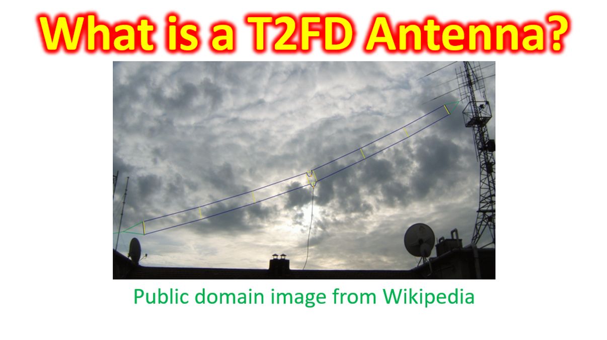
T2FD is short form for Tilted Terminated Folded Dipole, also known as Balanced Termination Folded Dipole antenna and Broad Band Terminated Dipole. At the outset let me thank SM0AOM for introducing the concept to me. It can perform as a broad band antenna for almost the whole of the HF spectrum up to 30 MHz. But it is a compromise antenna with gain much lower than a resonant dipole antenna on the lower bands. Efficiency of the T2FD antenna is low up to 30% of RF energy being lost in the resistor. It was being used by radio amateurs in 1950s and later went out of use, only to return with allocation of multiple new frequency bands which are not even integer multiples of previous frequency bands. One cited advantage is the feasibility of deployment at limited spaces where dipole antennas for lower bands are not feasible.
Designs with longer total length give more efficiency at lower frequencies at the expense of more space of land needed for installation. One commercial brand which I came across had 25 m length for coverage from 160 m to 10 m bands. That brand had a 4:1 balun at feed point. There are reports of indoor antennas which are just 24 feet long operating on 14 MHz and above for TX with additional receive on 7 MHz. Basic design of T2FD has a span nearly half the wavelength of the lowest operating frequency and has an upper and lower conductor. Distance between the upper and lower conductors will be one percent of the wavelength, for which separators are needed. Separators at the ends are tied to supports using non-conducting ropes. Both conductors are connected at both ends using wires along the end dowels.
Feed point is at the middle of the lower conductor and has an impedance of about 300 Ohms, requiring a 4:1 balun for matching with a 75 Ohms cable. Upper conductor is terminated in the middle with a resistor to match the characteristic impedance and rated to safely absorb about one third of the RF power output. The resistor absorbs more power towards the lower end of the design frequency range. Electrical termination is the practice of ending a transmission line with a resistor to prevent reflection of power from the ends back to the source. Mounting the antenna in a slanting fashion gives better omnidirectional performance.