Trying to Build a 40 Meter Inverted V Dipole in Zig-Zag Fashion!
Trying to Build a 40 Meter Inverted V Dipole in Zig-Zag Fashion!
In my first stint on amateur radio I have used inverted V and horizontal dipole antennas at my parents’ home and worked a lot of DX on CW, including a few stations from the United States, on 40 m. At my present location, there is not enough space for a horizontal dipole or even a true inverted V antenna. So I am going to try out a compromise setup with partial inverted V and partial zig-zag mounting. Moreover the spacing from parts of the roof will be minimal or none at some places. I have bought a 3 m long CPVC hot water pipe to keep as a non-conducting mast on the first floor balcony. It is a bit stiffer than the usual PVC pipes used for cold water, still nowhere near a galvanized iron pipe!
As the first step, I measured out 2.5 sq. mm. insulated copper wire, 10 m for each side, with a little bit extra for the knots and potential trimming during the tuning process, as recommended by online resources.
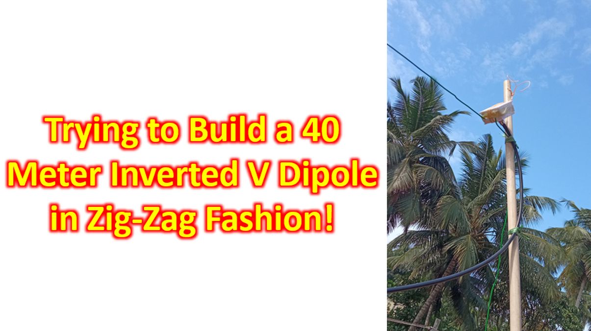
SO 239 connector was fixed inside an electrical cobox using tapes as it is a prototype. Soldered the antenna wires to the central conductor and base. Wires had been looped through the holes of the cobox for relieving tension on the solder joint.
Electrical cobox was closed with the built-in screws which it had, planning to mount the antenna. I have not made a balun yet, to match the balanced antenna to the unbalanced coaxial cable. Coaxial cable I am using is a 30 m length of RG 213, which came pre-crimped with PL 259 connectors at both ends. One end is connected to the SO 239 on the HF radio and another end to the SO 239 on the antenna junction cobox. Now comes the most important step of tuning, which I plan to do on another day as it is expected to be quite tiresome, with repeated testing and trimming, especially as this is a compromised mounting!