Balanced and Unbalanced Transmission Lines in Amateur Radio
Balanced and Unbalanced Transmission Lines in Amateur Radio
Typical example of a balanced line is a ladder line, which is often used to connect to a centre fed Zepp antenna for multiband operation. It has two parallel conductors spaced by insulators. Air acts as the dielectric between the conductors. Spacers at 12 inch intervals could be of ceramic or fibre glass. Impedance of the line may vary from 300 to 600 Ohms. Impedance is calculated using the formula Z = 276 log (2S/d) Ohms, where Z is the feeder line impedance, S is the centre to centre distance between the conductor wires, and d the diameter of the conductors. The dimensions are in inches. In case of a balanced line, neither conductor is connected to the ground. A matching tuner circuit is used between the 50 Ohms transmitter and the 300-600 Ohms ladder line.
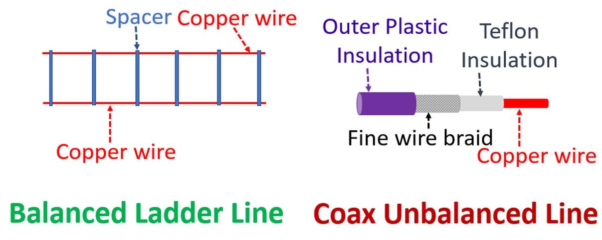
Typical unbalanced line is a coaxial cable, which has one central core separated from the outer conducting sleeve by an insulator like plastic or teflon. The sleeve is grounded at the transmitter. Current in the center conductor and that on the inside of the shield of the coaxial cable are equal but opposite. Due to skin effect, another current flows on the outside of the shield, from the connection point of the shield and antenna back to the connector on the transmitter, and hence to ground. This third current depends on the length of the transmission line. If the line length is an integral multiple of half wavelength, it has a low input impedance and permits the flow of current. This can be prevented by the use of balun or balanced to unbalanced transformer. Balun provides a fixed ratio of impedance transformation and limits the flow of unbalanced current flowing on the outside of the shield. Information courtesy, ARRL website.