Line Isolator or RF ‘Choke’?
Line Isolator or RF ‘Choke’?
Few days back I had built an Inverted V Dipole Antenna for 40 Meter and mounted it in a zig-zag fashion due to dearth of space in my compound. I tried two different orientations and could not get a satisfactory result while checking into the local HF nets. Net controller was getting my signals very weak, though I was using up to 35 W on LSB. At the same time I was able to hear the net controller and most other stations loud and clear. I had tuned the antenna by trimming it for the lowest possible SWR on 7 MHz band and got reasonable levels up to 1.2:1 at the lower end of the band while it was 2:1 at the higher end of the band. It was then that I noticed that both the forward power and reflected power shown in the SWR meter were very low. It was much lower than the power that I had set in my radio. Then I started wondering whether the coil of surplus RG 213 in my shack was the culprit.
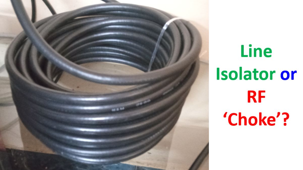
Initially I had thought that it would act as a line isolator for the dipole antenna as I had not built any balun. I had about 23 turns of RG 213 as coil with diameter of about 20 cm. I had used a 30 m long RG 213 cable as that was the ‘standard length’ provided by the dealer with pre-crimped PL 259 connectors at both ends. Even though it was too long for my very low antenna, I thought I would keep the remaining part coiled within the shack, for time being. I was not confident of crimping a PL 259 connector after splicing the surplus cable. After seeing the poor performance of my system I decided to change it for a 10 m HLF 200 cable with pre-crimped PL 259 connectors at both ends. To my surprise, that thin cable performed much better than the thicker RG 213 cable while checking into HF nets.
Another peculiarity which I noted was that after changing the cable, the SWR dropped to 1:1 at the upper end of the band while it became 1.4:1 at the lower end of the band. Power output shown on the meter was much better after change of the cable. I could not believe that the improvement in performance was solely due to the decrease in length of the cable, reducing loss in the cable. Length of surplus cable would be around 15 m in the coil which should theoretically produce a loss of around 1 dB only. My view of the paradoxical poor performance of a better cable is that the coil was choking off the RF output of my radio. I atttribute the change in SWR in opposite direction to probable ‘over tuning’ with the coil in place, which would have made it like an ‘electrically shortened loaded coil dipole‘.
Removing the coil would have shifted the resonant frequency upwards. If the coil was not there, I would have trimmed the antenna lesser during the tuning process. Anyway, as the SWR at the middle of the band was less than 1.1:1, I accepted the current situation, without going for any retuning by lengthening the antenna, which would be more cumbersome than trimming. To prove my theory I will have to re-introduce a corresponding inductor in the antenna circuit and test again. As I do not have a NanoVNA or any other antenna analyzer, I decided to try out the current setup for some time before making any further changes. What I have discussed is my view, which may be wrong and I am open to corrections and suggestions.