Know Your Coaxial Cable Well!
Know Your Coaxial Cable Well!
Coaxial cable is the most common feedline used to connect amateur radio to the antenna. Coaxial cable consists of an inner conductor surrounded by a conducting shield, the two being separated by an insulating material which acts as a dielectric. There is a protective outer sheath in addition to these. It is called a coaxial cable because the inner conductor and outer shield share a geometric axis. Coaxial cables have been in use since the second half of nineteenth century. An ideal coaxial cable has its electromagnetic field only in the space between the inner and outer conductors. This allows the coaxial cable to run near metal objects without power losses. There is also shielding from external electromagnetic interference.
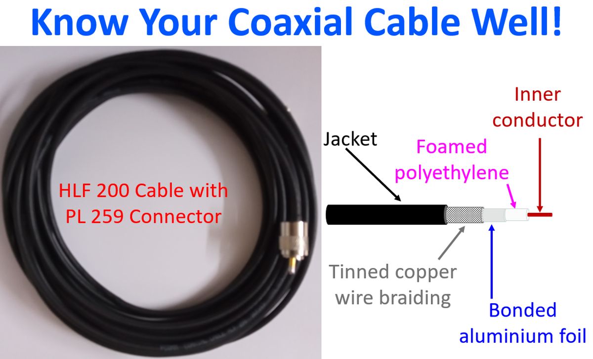
Usual coaxial cables used in amateur radio have a solid inner conductor surrounded by an insulating material, which in turn is enclosed in shield of one or more layers of woven metallic braid. Some varieties like the HLF 200 cable in the illustration has a bonded aluminium foil between the dielectric and the outer shield. Special variety of coaxial cable known as hardline has a shield made of solid tubing and is hence thicker and difficult to bend. Outside of the shield of the coaxial cable is usually connected to the ground and the central conductor carries the signal voltage.
Impedance of coaxial cables used for amateur radios is typically 50 Ohms. Though the impedance of a typical half-wave dipole antenna is mentioned as 73 Ohms, if the antenna is held horizontal at about half wavelength from the ground, feedpoint impedance drops and matches well with a 50 Ohms coaxial cable. Very often cables named as RG 8/U or RG 213 may be used for amateur radio. RG stands for Radio Guide and U stands for Universal. RG 6/U is a 75 Ohms cable used for television applications. RG 8/U has an impedance of 50 Ohms, inner conductor of 2.17 mm and outer diameter of 10.3 mm. RG 8X is a thinner version with inner conductor of 1.47 mm and outer diameter of 6.1 mm.
RG 58/U has an impedance of 50 Ohms, inner conductor of 0.81 mm and outer diameter of 5 mm. RG 213 also has 50 Ohms impedance and has inner conductor of 2.26 mm constituted by 7 conductors of 0.75 mm. It has an outer diameter of 10.3 mm. RG 6/U has polyethylene foam as dielectric while RG 8, 50 and 213 have solid polyethylene as dielectric. RG 213 has lower losses than RG 58. Earlier I was using RG 213 for my VHF equipment.
LMR 200 is a 50 Ohms cable with inner conductor 1.12 mm, outer diameter 4.95 mm and polyethylene foam as dielectric. LMR 400 will have inner conductor of 2.74 mm and outer diameter of 10.29 mm, with same impedance and type of dielectric. Core is copper clad aluminium.
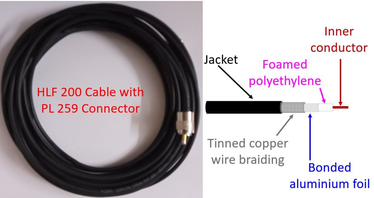
I am currently using HLF 200 for my VHF equipment, which is supposed to be equivalent to LMR 200. It has an inner conductor of 1.12 mm diameter. The outer condutor of tinned copper braiding has a diameter of 3.66 mm. Diameter of the polyethylene dielectric is 2.95 mm. There is a bonded aluminium foil between the dielectric and the outer braiding. External jacket has a diameter of 4.95 mm. The upper cutoff operable frequency mentioned is 3 GHz. In fact I have used the same cable for my UHF experiments also. HLF 200 cable has a characteristic impedance of 50 Ohms.
HLF 200 is a light cable, easy to handle, having a minimum bending radius of 19.1 mm. Peak power rating is 2.5 kW, though I need only a maxiumum of 25 Watts for my VHF equipment. Attenuation value is given as 10.8 dB per 100 meter at 100 MHz and 22.8 dB per 100 meter at 450 MHz. Currently I am using only 10 m of HLF 200 cable, so that the loss in the cable for even UHF amateur radio band will be below 2.28 dB. HLF 200 cable has a capacitance of 80.4 pF per meter.