Combining My VHF and UHF Yagis Into a Single Feeder Dual Band Satellite Yagi
Combining My VHF and UHF Yagis Into a Single Feeder Dual Band Satellite Yagi
I had built seven element VHF and five element UHF Yagi antennas earlier. Both had gamma match for the driven elements. Later when I shifted focus from terrestrial repeater operations to satellite operations, I had built a Moxon Dual Band Yagi with single feeder for satellite operations. I noted the convenience of single feeder dual band Yagi antennas as I did not have a diplexer suitable for base station operations. Though I could work Amateur Radio on International Space Station comfortably with the Moxon Yagi, the gain was not enough to work other LEO satellites orbiting at an altitude higher than ARISS. Those satellites have a bigger footprint and is more likely to give some DX contacts from my region. Hence I decided to go for a five element VHF plus eight element UHF dual band, single feeder Yagi, possibly recycling some of the elements of my previous Yagi projects.
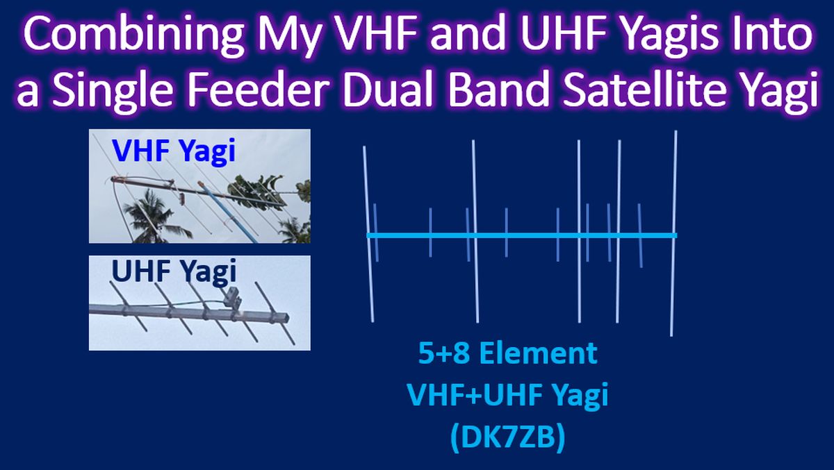
I came across a design by DK7ZB at his QSL Net page in which he added eight UHF elements to a five element VHF Yagi design, in such a way that the UHF elements couple passively with the VHF driven element, which works as UHF driven element also, as a third harmonic. In a description of his four element VHF plus five element UHF Yagi, he had mentioned that it works on UHF with an SWR of 1.5:1. There will be three current maxima in the 3/2 lambda radiator when VHF driven element functions as a UHF driven element. Hence there will be three forward lobes of radiation, with 5.39 dBd, 4.35 dBd and 5.39 dBd gain respectively. As per design, the five element VHF plus eight element UHF Yagi will have 8.45 dBd gain on VHF and 8.86 dBd gain on UHF. The calculated front to back ratio is 24 dB on VHF and 14 dB on UHF. Both these seemed quite reasonable for my satellite operations.
But the disadvantage I found was the beam width in horizontal plane. The 3dB angle in horizontal plane was only 28.2 degrees on UHF and 51 degrees on VHF. Corresponding values for the vertical plane were 54.2 and 64.3 degrees respectively. From these values, I presume that tracking a fast moving low earth orbit satellite will be more difficult on UHF compared to VHF. As I do not have an antenna rotator and have been using my Moxon Yagi on a fixed elevation and azimuth, the proposed new antenna will reduce the workable duration of the pass, though it will increase the gain and may increase the chance of working satellites at longer distance.
DK7ZB design had used 3.2 mm aluminium welding rods. As these were not available locally, I had used 3/8 inch aluminium pipes for my previous antenna projects. That would correspond to about 9.3 mm. A version redesigned by SQ9VPA was available for 10 mm elements on the same page. So that it would approximate for my use with 3/8 inch aluminium pipes. Only snag was that SQ9VPA modification had 12 mm for the driven element. Anyway, I decided to try with 3/8 inch aluminium pipes itself, as 12 mm was not available locally.
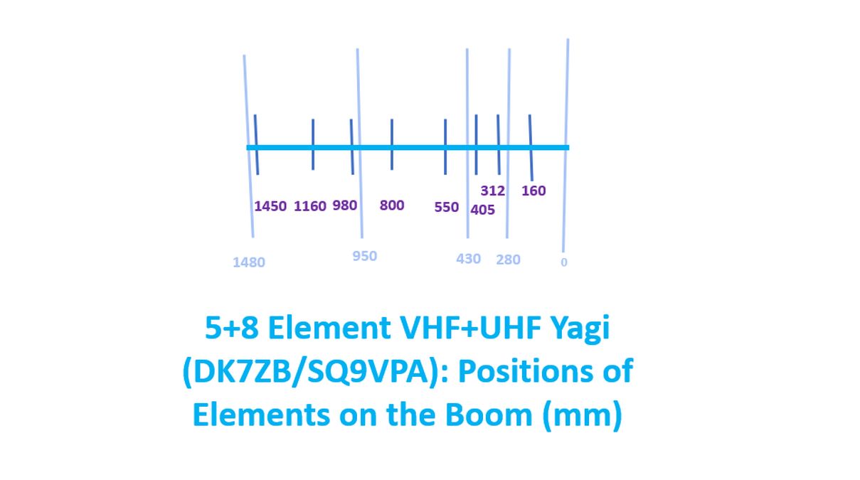
SQ9VPA modification had also a portable version in which the antenna could be assembled on two smaller booms and joined together at the time of use. DK7ZB has mentioned that the design is optimised for the lower CW/SSB end of the bands. That was another snag, as I am planning to use the antenna for the upper end of the band for satellite operations, that too on FM. Total boom length was nearly 1.5 m and needed a 20 mm PVC pipe, while my previous VHF and UHF Yagis had 1 inch square aluminium boom. My next step will be to compare the lengths of the elements and find out how many of the previous VHF/UHF Yagi elements can be recycled for the proposed dual band single feedpoint Yagi antenna. I will need a fresh boom as well.