Homebrewing of My First VHF Seven Element Yagi Continues
Homebrewing of My First VHF Seven Element Yagi Continues
Initial steps of Homebrewing of My First VHF Seven Element Yagi was discussed earlier. It is a KA0NAN/VU3NSH design from hamradio.in, one of the best ham radio sites from this region, by VU2ITI, with whom I used to have regular amateur radio contacts on HF nearly four decades back, when I was active on HF. Last time I had completed cutting the elements for the seven element Yagi, 7.25″ circular 3/8″ aluminium pipe for Gamma stub, boom for the antenna and the shorting bar of 1″ square aluminum pipe. As 50 Ohms coax is not available locally, I am planning to use a piece of 75 Ohms RG 6 coax and try my luck. Incidentally, RG 6 is available in plenty in this locality as it is being used for cable TV. My presumption is that as the coax piece is used essentially as a variable capacitor along with the 7.25″ circular 3/8″ aluminium pipe, for the tuning part of the Gamma match, it may still work for my beam.
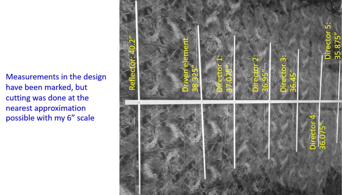
Reflector was cut at 40.2″ as given in the design. Driven element length was given as 38.325″. First director length is given as 37.075″, second director as 36.95″, third director as 36.45″ fourth director as 36.075″ and fifth director as 35.875″. I do not have the precision instruments to cut it at the third decimal level! All I have is a Hacksaw and an ordinary 6″ measuring scale and a measuring tape. So I have cut the elements to the nearest division on the scale. I am aware that it may not do well when measuring the SWR and checking the performance. But that is the best I can, in this homebrewing project. Moreover as I am using the hacksaw for the first time, I could see that most of the cut edges do not look anywhere near a machine cut element. The edges are quite ragged! 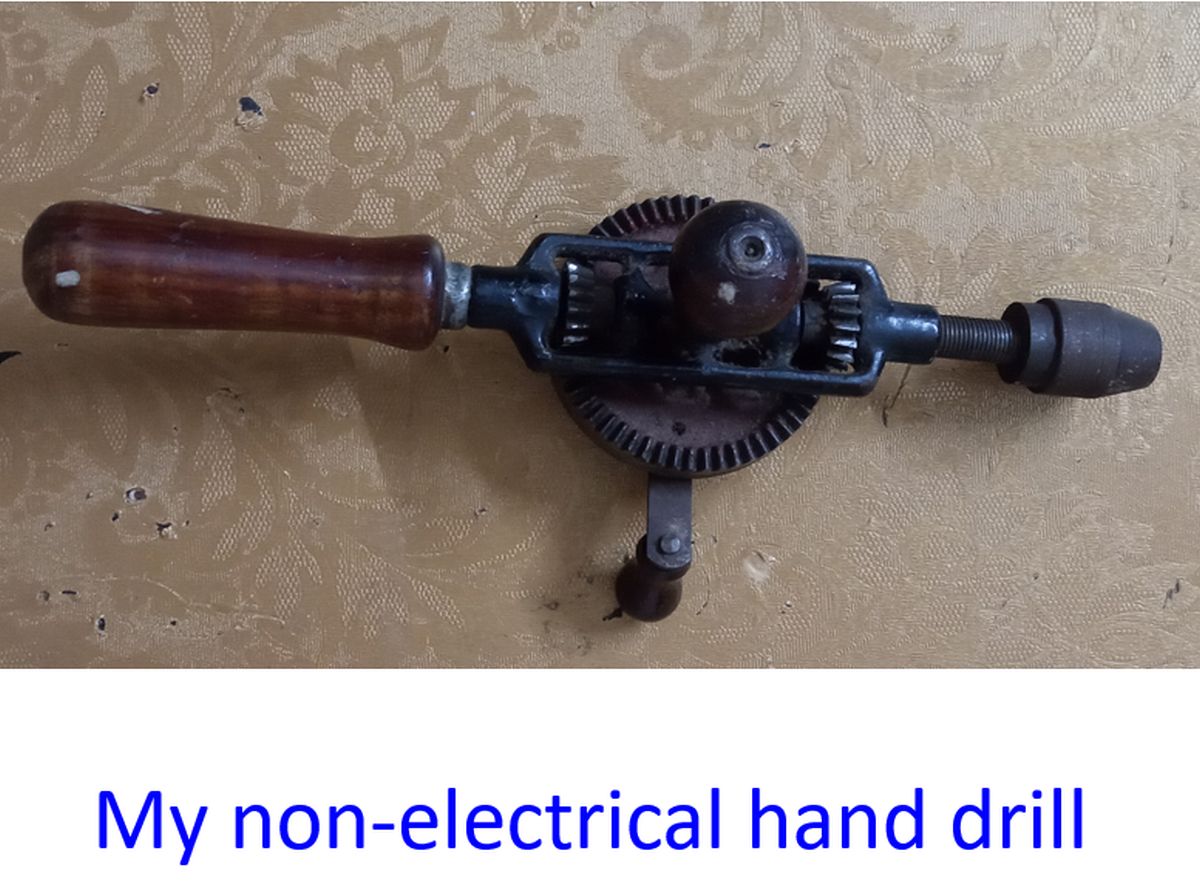
Next task was using the electrically driven hand drill, that too for the first time. I had used the non-electrical hand drill about 4 decades back for homebrewing may radios, when I did not have the luxury of an electrically driven hand drill. Here again I had problems, the drill bit would slip away from the site I have marked for drilling. Gradually my aim for drilling holes at the right spot improved.
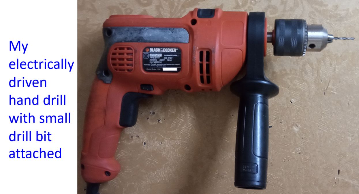
I would drill a hole with a smaller sized drill bit first and then go for the right sized drill bit so that the slipping problem was less. Another way was to start at a very slow speed and make a small pit on the metal with the drill bit before going for higher drill speeds. Of course, all these would have been tried and perfected by others who are well trained. There could also be better methods which professionals use, which I have not been trained in. In between a couple of drill bits broke off and fortunately I had a spare one. Anyway, none of the holes which I drilled were perfect, with most being oblique and ragged at the opposite end.
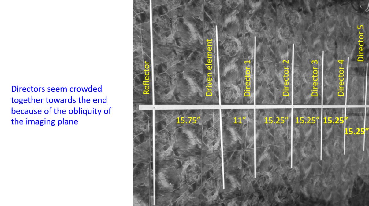
Now I had to mount the elements on the boom. I marked out the positions for drilling the holes for the screws on the boom. Reflector – driven element distance was given as 15.75″, driven element – first director distance was 11″. Distance between all the successive directors was 15.25″. Again I had to go for the best possible approximations due to the limitations. Here the drilling process was easier as only a much smaller drill bit was necessary.
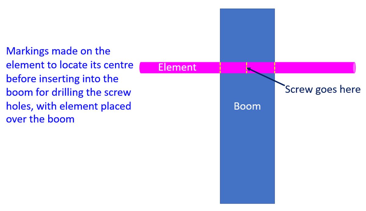
I would mark out the middle of the element with a screw driver using a measuring tape and then keep the element in the intended position on the beam. After that I would mark both sides of the boom on the element so that I can know that it is exactly in the centre when inserted within the hole in the side of the boom. Then I would drill a hole in the boom through the element for inserting a 3/4″ brass screw. Ideally I should use a stainless steel screw for long term performance in the rainy season. But this being a prototype, I did not go for a stainless steel screw which is difficult to procure while I had the brass screws ready at home.
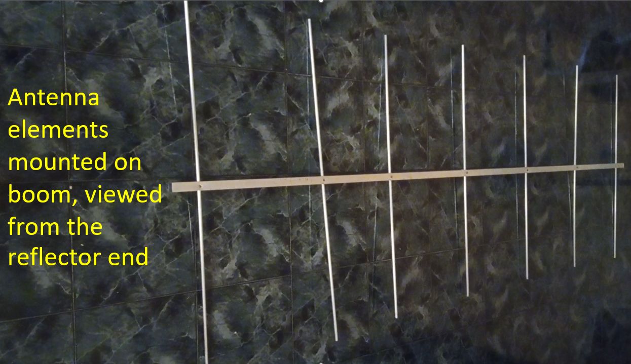
After fixing all the elments on the boom I could see that all the elements are not in the same plane, thanks to the oblique holes a true ‘amateur’ had drilled in the boom! So it is somewhere between a cross-yagi and a regular yagi, as I would put it in jest. May be next time when I homebrew a UHF Yagi with the remaining material, I would achieve a better precision. Now I have to think of making the Gamma match and the coax connection, which I am planning to do another day.