Crimping PL 259 Connector to RG 213 Coaxial Cable
When I started off in 1985 as an amateur radio operator, I was not aware of crimping PL 259 connector and had a tough time soldering the outer sheath of the coaxial cable to the outer conductor of PL 259. This time I thought of attempting crimping a PL 259 connector on to the cut end of RG 213 cable. Other end had a pre-crimped PL 259 connector. Here are the three components of the PL 259 connector seen separately. Heat shrink sheath VW-1 which came along with PL 259 has already been inserted over the cut end of RG 213.
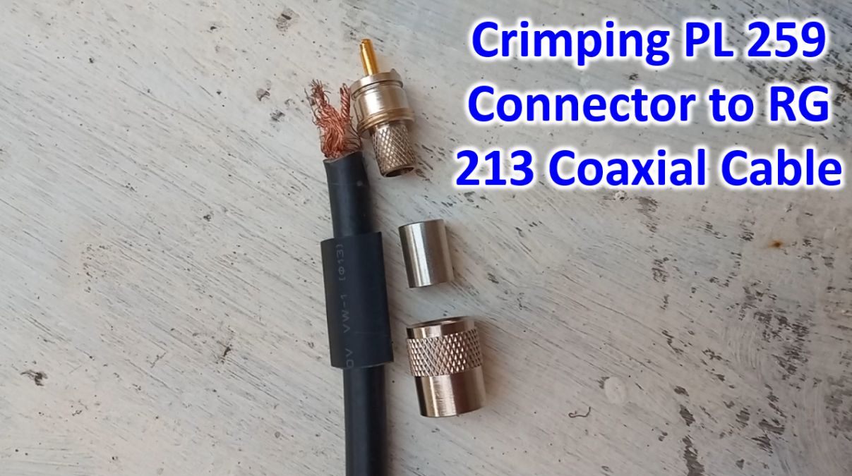
Outer most screw in part of PL 259 was then inserted over the RG 213 coaxial cable.
Length of outer sheath of the RG 213 to be removed was marked using a small scalpel blade.
I had to use a bigger knife to carefully remove the outer protective sheath of the coaxial cable. After that, the tubular crimping part of PL 259 was introduced over the coaxial cable, on the braid, after removing a thin polyethylene covering over it.
Innermost part of PL 259 was then introduced inside tubular part in such a way that it goes between the metallic braid of the coax and the thick inner dielectric. The inner conductor of RG 213 reached up to the tip of the inner conductor of PL 259 plug.
Outer part of PL 259 connector was then slided over the heat shrink and gradually turned to reach a little away from the tip as seen here. Copper wire strands in the inner conductor of RG 213 can be clearly seen at the tip.
Inner conductor of PL 259 was soldered carefully to the copper wire strands of RG 213 using a 65 W soldering iron, soldering paste and solder wire. Tip of the soldered region was carefully scraped a little so that it would fit smoothly withing an SO 239 connector of the balun. Otherwise extra solder at the tip will cause splaying of the inner conductor of SO 239. Multimeter was used to make sure that there was no continuity between the two conductors of PL 259. After that PL 259 at the other end of RG 213 was shorted using a wire and continuity tested at this end to make sure that there is no open circuit.