First Look at EZNEC Pro+ 7.0 Antenna Modeling Software
First Look at EZNEC Pro+ 7.0 Antenna Modeling Software
So far I have been trying out antenna designs built and tested by radio amateurs world wide. I have been hearing of antenna modeling software while reading about most of the designs, but never ventured to have a look at one. As ARRL puts it, antenna modeling was the domain of scientists and engineers with expensive antenna ranges covering acres of land, along with expensive equipment. But now with ubiquitous availability of personal computers and antenna modeling software, it has become a popular amateur radio activity. Antenna modeling gives you advance information even before you start building your antenna, like feed point impedance, SWR and radiation pattern in three dimensions. Having experienced tough time tuning three of my VHF/UHF antennas in the past few months, I thought of looking at antenna modeling software before beginning to assemble my new VHF/UHF dual band single feedpoint antenna by DK7ZB design.
Downloaded EZNEC Pro+7.0, which is now free, even though without support as the author W7EL has retired. Printable manual in pdf format was also downloaded for easier reading on computer screen. EZNEC Pro2+ v. 7.0 which I have installed has a built in NEC-2 calculating engine. It can also use external NEC-4.2 and NEC-5 calculating engines. Hence EZNEC is an interface for the Numerical Electromagnetic Codes (NEC), developed by several people over the years, funded by the US Government. I have not purchased any of these external NEC versions, though the author has recommended purchasing NEC-5. The built in internal calculating engine in EZNEC Pro2+ v. 7.0 is a modified version of NEC-2 available in public domain.
This is the intial screenshot which comes up when you open EZNEC software from your desktop. As I was new to the software, I started off with the Help menu at the top right corner. I read through the Help file till I reached the Test Drive Introduction and then the Along The Straightaway page. That is the page where an initial test drive of a 20 m dipole antenna is described.
Clicking on Open menu takes you to the directory in which sample antenna files are stored in your computer, within the EZNEC directory. For a test run of the 20 m dipole antenna, the file named Dipole 1 can be opened and the instructions in the help followed.
I wanted to try out the VHF section of the planned dual band single feeder Yagi, to simplify the learning process. I changed the name of the antenna from Dipole in free space to Four Element VHF Yagi by clicking on the antenna name and typing in the dialogue box and clicked OK.
Next I clicked on Frequency and changed it to 145.990 MHz, the uplink frequency of Amateur Radio on International Space Station, which I have been able to work maximum times so far and clicked OK.
Immediately, the frequency and corresponding wavelength appeared on the main EZNEC screen, as 145.99 MHz and 2.05351 m respectively.
Next I clicked open the Wires menu and changed the default diameter of the wire from 1 mm to 9.3 mm of the aluminium pipe which I had planned for the antenna. The diplay in the field was initially in red colour, which changed to black after saving using Print/Save Wire List… from the Other menu.
Next I accessed Add.. in the Wires submenu.
Entered 4 in the Number of wires to add dialog box as I was planning for a five element VHF Yagi. Place in the list above wire was left as the default 2 and clicked OK. Immediately a warning appeared in red colour that the wires have zero or near zero length.
The number of Wires in the main display changed to 5 Wires, 55 segments.
Next I changed the Y axis dimensions of Wire 1 to half the measurement shown in design for the reflector element, with End 1 being negative and End 2 being positive. Similarly dimensions of other wires were also added. Each time there was error display mentioning that remaining wire lengths were zero. Next error display was that wires were overlapping. This was taken care of by changing X axis dimensions to position of the elements on the boom. Exited the wires menu after saving from the Other menu as before.
Just to know my progress in the use of EZNEC, I clicked on FF Plot in the main screen, meant for the Far Field Plot. I got a display as shown on the left side of the screen. I have changed the colour of the Primary Trace using the Colors option in the Options menu and then using Total Field. Immediately I could understand I have far from succeeded as the Azimuth Plot was nothing like that expected for a five element Yagi. Front to back gain was shown as 0.22 dB, which is obviously not what is expected.
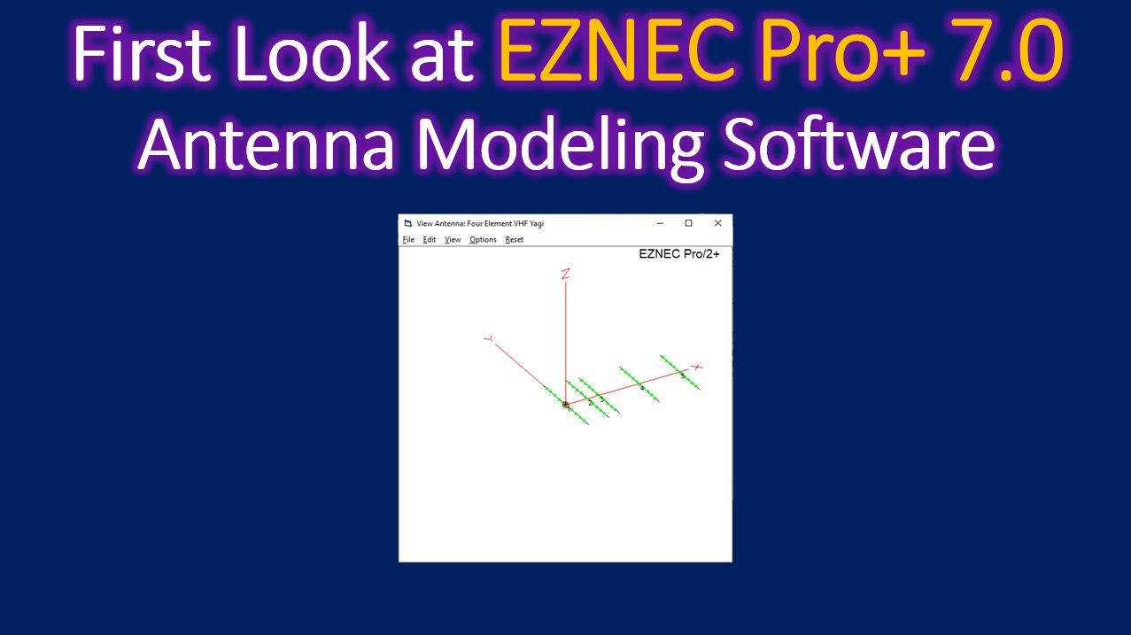
This was the view of the antenna generated by clicking on View Ant. It shows the antenna along with a display of X, Y and Z axes, though this is a single plane antenna. In first look of the ENZEC software I have gone wrong at possibly multiple places.
When I had a look at the sample file for 20 m five element antenna, there were 55 wires and 95 segments while my five element VHF antenna had only 5 wires and 55 segments. Obviously something grossly wrong in my methods. Decided to go through the Help file in a little more detail and troubleshoot.