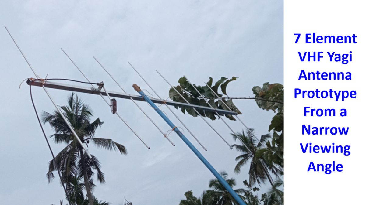
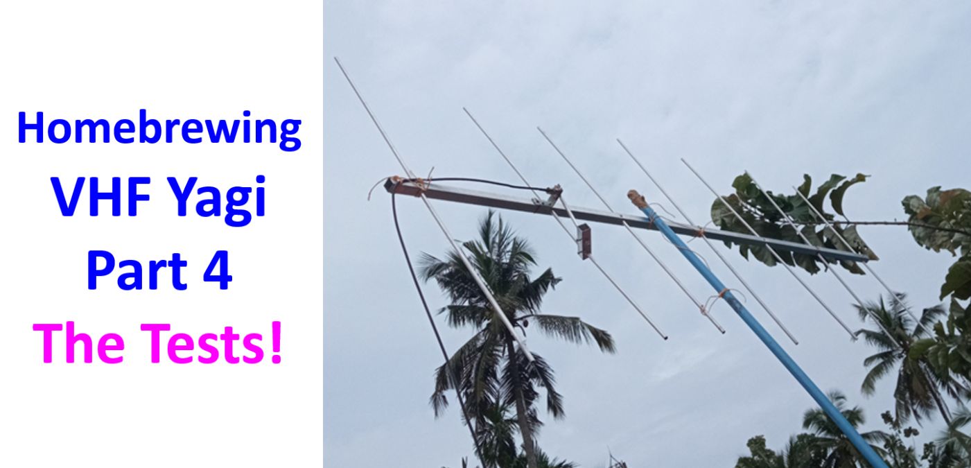
Homebrewing VHF Yagi Part 4, The Tests!
Homebrewing VHF Yagi Part 4, The Tests!
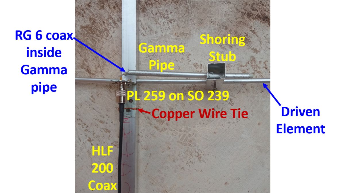
One more hole was drilled in the L shaped metal piece for holding the SO 239 antenna connector to be fixed on the boom of the 7 element VHF Yagi being homebrewed. It was then fixed over the boom near the position of the driven element. 7.25 inch of 75 Ohms RG 6 television cable was cut and placed inside the circular 3/8 inch aluminium pipe of same length for the tuning part of the Gamma match. As the RG 6 cable was thinner than the RG 213 given in the design, I retained outer sheath of the coax and the shield to see how it works. The metallic shield and the alumninum foil inside it was practially shorting with the aluminium pipe at one end where the plastic sheath was removed to expose the inner conductor. The inner conductor of the coax was soldered to the inner conductor of the SO 239 connector.
The 7.25 inch alumuminum pipe was fixed on the driven element with a sliding mechanism using a short piece of one inch square aluminium pipe in a way that it was almost 1.5″ separated from the driven element. It is meant to be slided for tuning the Gamma match as the shorting bar. Two screws were also fixed on the shorting stub, one to the Gamma pipe and one to the driven element so as to ensure good electrical contact as I was using a square aluminium pipe instead of a a solid piece of aluminium. I had 10 m of HLF 200 coaxial cable pre-crimped with PL 259 connectors at both ends. One end was connected to the SO 239 on the VHF Yagi and other end to the SWR meter. Patch cable from the SWR meter was connected to my quarter century old VHF base station which would work only on low power.
As a non conducting piece of pipe could not be found at that time I attached a piece of surplus multi-would board which was quite thin, to the centre of the antenna boom, perpendicular to it, as the upper part of the mast. As it would not support the weight of the antenna and started bending, I had to reinforce it with a metallic telescopic pole used for painting higher up in the walls. All attachments were made using nylon wires and were not very secure like stainless steel clamps, which I did not get from the local market. Put the antenna up about 9 feet, inside a first floor room and checked the SWR. I was shocked to see an SWR of about 10:1. Stopped work for the day as I was quite tired, to resume the next day.
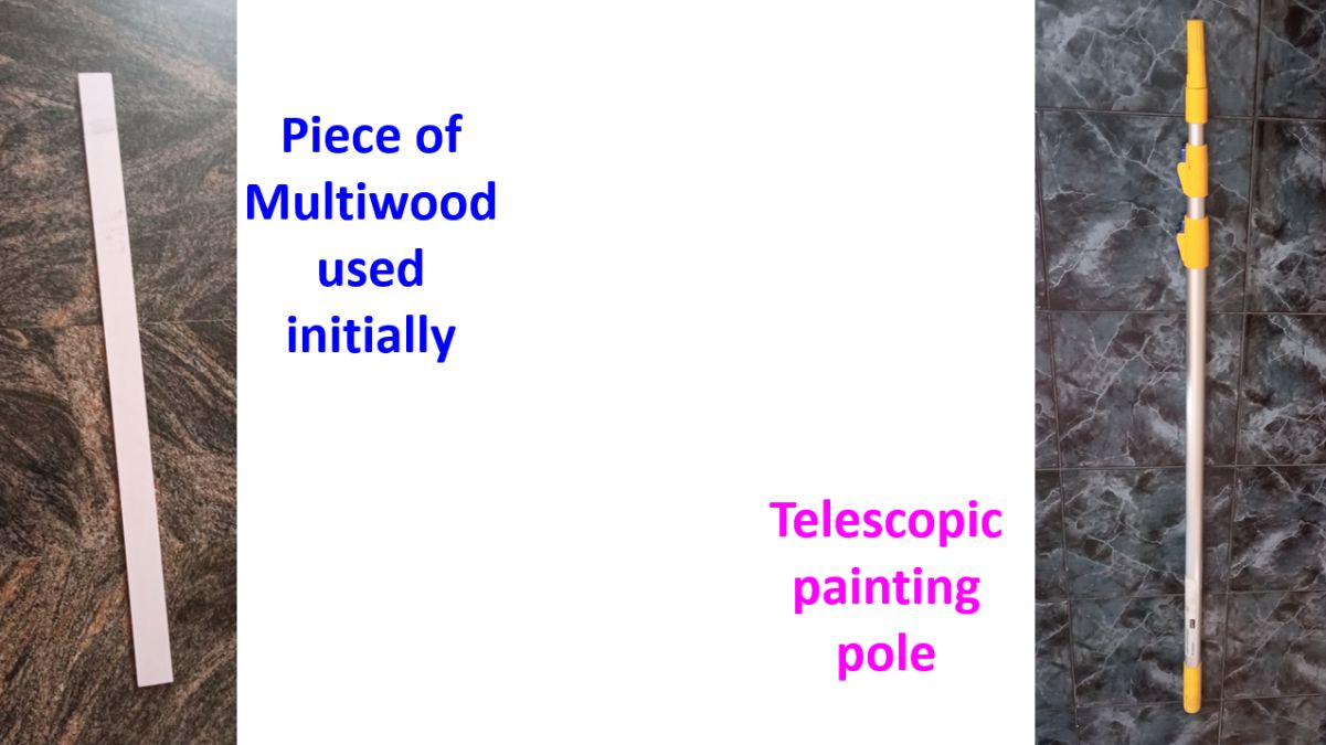
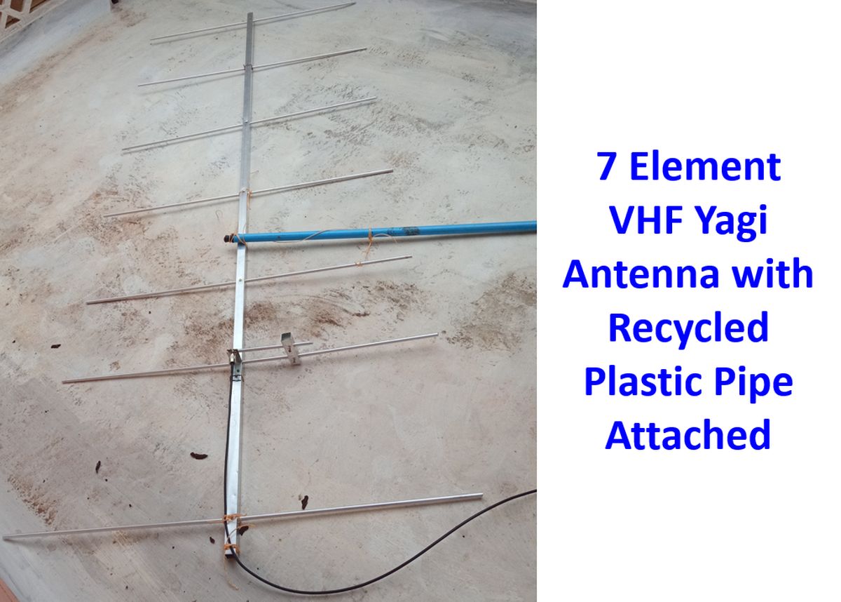
Meanwhile I had talked to a senior ham who told me that RG 6 coax also should do the job if you adjust the tuning of the Gamma match. Several possibilities for initial failure were thought of. Checked all the connections by multimeter and ensured that the contacts to the boom of the elements and antenna contacts were good. The multi-wood piece was replaced by a stronger piece of plastic pipe recycled from an old mop so that the metallic telescopic pole would be at least two feet away from the boom, though the recommendation is three feet. When the antenna was rehosted inside the room an SWR of about 2:1 was obtained and I could access two repeaters one at about 4 km and another at about 30 km. As there was a fan and a multi-gym near the antenna, with plenty of metal, I decided to conduct further tests outside the room. Moreover, the SWR was shooting back to 10:1 intermittently, and I did not know the reason.

In two places where the screws seemed to be a little loose, additional ties were given with bare multi-strand copper wire, presuming that it could be a loose contact causing the intermittent jumps in SWR. The metallic telescopic pole was tied with nylon wires to the parapet of the first floor balcony and the 7 element VHF beam antenna raised to about 6 m from the ground, still within the height of the building. Again SWR was 2:1, but performance was better in terms of reception of repeaters. With the antenna pointing South, Tirur repeater about 30 km away was easily accessed while there was no access to Vadakara repeater about 40 km North. I was happy that beam antenna is doing its function with significant front/back ratio. Calicut repeater which is only about 4 km away, could still be accessed well, with the beam pointed almost perpendicular to it, presumably because of proximity. When the beam was turned North, Vadakara repeater could be accessed, while I lost access to Tirur repeater in the opposite direction, again showing the directional gain of the 7 element VHF Yagi.
As the SWR was still not in the acceptable range, the 7 element VHF Yagi antenna was lowered, to adjust the Gamma match. While attempting to adjust the Gamma match, the soldered joint between the inner conductor of the coax and the SO 239 connector broke! It was because the shorting stub was not well fixed, being a square lumen pipe than a solid piece of aluminum. The shorting stub was also at an angle because I had fixed the L shaped metal piece with the SO 239 connector too close to the driven element. Pushed the inner conductor of the coax back into the SO 239 without soldering and apparently ‘fixed it’. The shorting stub was pulled back a little as ‘tuning’. Of course it did not work and the SWR was higher at 2.5:1. With a lot of work done single handedly, decided to call it a day and continue on another day.