How Does a Yagi-Uda Antenna Work?
How Does a Yagi-Uda Antenna Work?
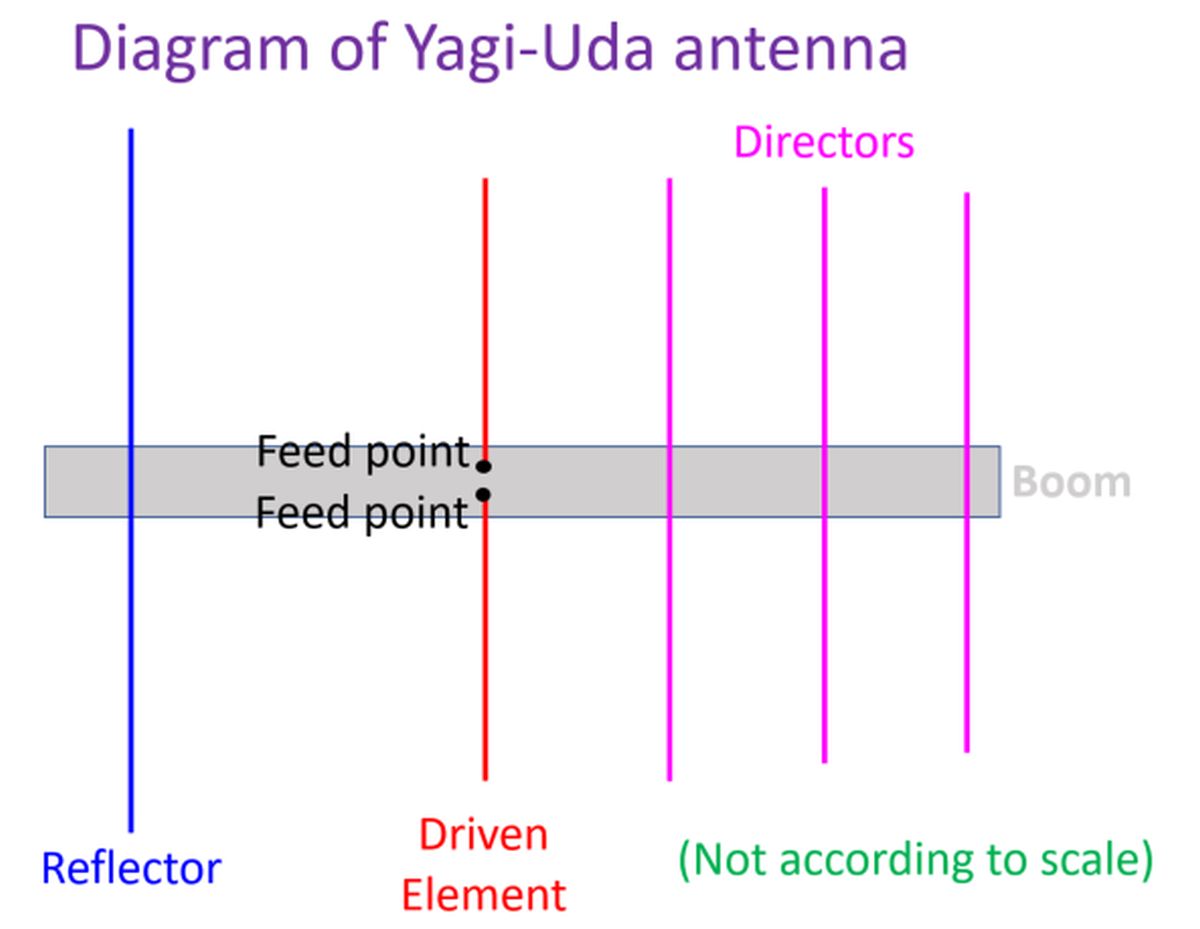
Yagi-Uda antenna is very popular in Amateur Radio or Ham Radio. It was also a common sight on housetops before the era of cable TV and satellite TV. It consists of a driven element and a variable number of parasitic elements on a boom. The driven element could be usual dipole or a folded dipole. Element behind the driven element is the reflector. Elements in front of the driven element are called directors. Typically the reflector is longer than the driven element while directors are progressively shorter than the driven element. Output of the radio is fed only to the driven element.
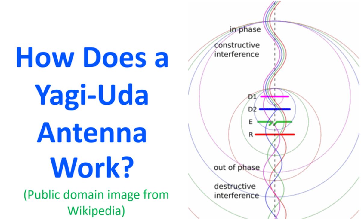
The animation illustrates how a four element Yagi-Uda antenna works. There are two directors and a reflector in addition to the driven element dipole. The parasitic elements act as resonators by absorbing and re-radiating the electromagnetic waves from the driven element, with a phase difference. There is constructive interference of these electromagnetic waves in the forward direction as they are in phase and destructive interference in the reverse direction as the waves are out of phase. Net effect is a stronger signal in the forward direction and a weaker signal in the reverse direction. This is usually mentioned as the forward/backward ratio of the antenna. In the animation, the signals are colour coded similar to the antenna element for ease of recognition.
Yagi-Uda antenna is often called as a beam antenna in Amateur Radio. Due to the size, it is less often used on HF bands than on VHF and UHF bands. The number of elements practically feasible are also lower on lower bands. They are used with antenna rotators as good directional antennas. Yagi-Uda antennas can have gains upto 20 dBi and a front to back ratio up to 20 dB. Radiation pattern is linearly polarized, with horizontal polarization for a horizontally mounted antenna and vertical polarization for a vertically mounted one. Bandwidth of Yagi-Uda antennas is relatively narrow, with a narrow range of frequencies within a band at which it has good gain and operable feedpoint impedance.
The driven element or radiator can be a simple dipole with two quarter wavelength rods connected to either conductors of the feedline. In some versions it is a folded dipole, which has a higher impedance of around 280 Ohms. The television antennas of yester years with folded dipole used to be fed using a twin-lead transmission line with impedance of about 300 Ohms. Folded dipole will need a matching for amateur radios with impedance of 50 Ohms. Usual dipole has an impedance of around 70 Ohms. Spacing between the elements may vary from quarter wavelength to one tenth of a wavelength depending on the design.
Radiation pattern of Yagi-Uda antenna is along the axis perpendicular to the plane of the elements, towards the direction of the directors. As the parasitic elements have zero RF voltage at the centre, they can be directly attached to the boom. But this will electrically shorten them and usually a correction in length is needed to cover this. There are versions in which all elements are insulated from the boom as well. The two halves of the centre fed dipole have to be insulated in the location of the boom.