How to Make a Multi-Band Cubical Quad Antenna?
Building a multi-band cubical quad is a highly rewarding homebrew project that delivers excellent gain, a low angle of radiation ideal for DX on modes like FT8 or CW, and a noticeably lower noise floor compared to Yagis. A 2-element multi-band quad typically covers 20m, 17m, 15m, 12m, and 10m using a single boom, with concentric wire loops strung on the same set of spreaders. Here is a practical engineering approach to constructing one.
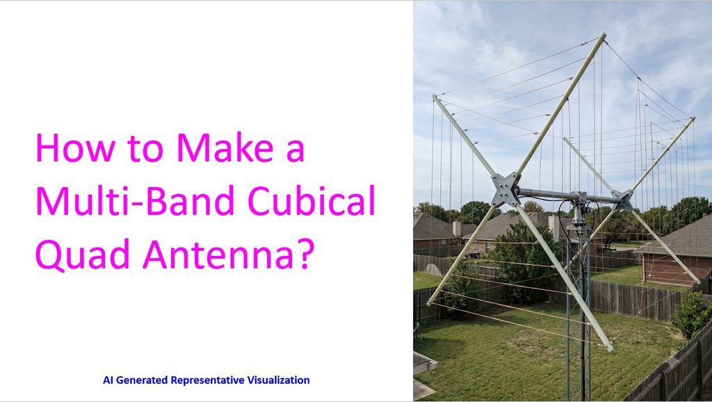
1. The Geometry and Spacing
A 2-element quad consists of a Driven Element and a Reflector. Because you are building a multi-band version, all five driven element loops will share one set of spreaders, and all five reflector loops will share the other.
The optimum spacing between the driven element and reflector is usually between 0.12λ and 0.15λ. On a multi-band quad, you cannot have optimal spacing for all bands simultaneously on a fixed-length boom.
- The Compromise Boom: An 8-foot (2.4-meter) boom is the standard sweet spot. This provides about 0.12λ spacing on 20 meters and about 0.23λ spacing on 10 meters, yielding excellent front-to-back ratios and gain across the entire high-frequency spectrum.
2. Element Length Calculations
A quad loop is a full-wavelength loop. The standard formulas for calculating the total wire length of the loops are:
- Driven Element: L (meters) = 306.3 / f (MHz)
- Reflector: L (meters) = 314 / f (MHz) (roughly 2.5% to 3% longer than the driven element)
Instead of cutting the reflector to a fixed length, many builders cut it to the driven element length and leave a small gap at the bottom center to attach a tuning stub (a shorted length of ladder line or parallel wire). This allows you to slide a shorting bar up and down to perfectly tune the reflector for maximum front-to-back ratio on each band.
3. Hardware and Materials
- The Boom: A 2-inch to 3-inch diameter aluminum tube, 8 feet long.
- The Hubs / Spiders: These are heavy-duty metal brackets mounted to each end of the boom that hold the spreaders at 135-degree angles (forming an ‘X’ shape). Cast aluminum or heavy-gauge steel spiders are essential for durability.
- The Spreaders: You will need eight spreaders (four for the driven elements, four for the reflectors). Fiberglass poles are the standard choice because they are non-conductive, flexible, and withstand UV degradation and monsoons much better than bamboo. 20-meter loops require spreaders that are approximately 13 feet (4 meters) long.
- The Wire: Hard-drawn bare copper or UV-resistant insulated copper wire (14 AWG or 12 AWG).
4. Feeding a Multi-Band Quad
A single, isolated full-wave wire loop usually presents a feedpoint impedance of around 100 to 120 ohms (often requiring a 4:1 balun). However, when you add a reflector spaced at ~0.12λ, the feedpoint impedance drops to roughly 50 to 60 ohms. This is highly advantageous because it allows you to direct-feed the driven elements with standard 50-ohm coax and a simple 1:1 current choke to keep RF off the shield.
For a multi-band configuration, you have a few options for the feedline:
- Single Coax with Common Feed (Tied Together): You can bring all five driven loops down to a single feedpoint at the bottom of the spider. This is physically the easiest and lightest method, but the non-driven loops can interact, slightly shifting the resonant frequency and radiation pattern of the active band.
- Remote Antenna Switch (Highly Recommended): Mount a weather-proof remote relay switch box at the boom-to-mast plate. Run a short coax jumper from each individual driven loop to the switch box, and run a single coax feedline down into the shack. This entirely isolates the loops from one another, ensuring predictable tuning and perfect SWR on all bands.
5. Assembly and Tuning Workflow
- String the Elements: Start with the 20m loop on the outermost perimeter of the spreaders. Work your way inward (17m, 15m, 12m) until you finish with the 10m loop closest to the boom.
- Mounting: Assemble the antenna close to the ground (on a short test mast) pointing straight up, if space permits, so you can easily access the feedpoints and tuning stubs.
- Tuning the Reflector: If you use tuning stubs on the reflectors, apply a weak local signal (or use an antenna analyzer/VNA) and adjust the shorting bar on the stub to find the deepest null off the back of the antenna.
- Check SWR: Check the resonant frequency of the driven elements. Because the corners of the loops are capacitive, the exact wire length might need a trim of a few centimeters to get the lowest SWR centered exactly where you operate most (e.g., the FT8 frequencies or SSB portions).
Once elevated, the cubical quad is relatively immune to detuning from ground effects compared to a horizontal Yagi or Inverted V, and it is exceptionally quiet on receive, which is highly beneficial if you are fighting localized RFI on the higher bands.
What about a single element multi-band cubical quad?
A single-element multi-band cubical quad is essentially a set of nested, concentric full-wave loops mounted on a single set of spreaders (a single ‘X’ hub). Because it lacks a reflector and a boom, its characteristics and construction differ significantly from a 2-element design.
Here is an engineering breakdown of how a single-element multi-band quad performs and how to build one.
1. Performance Characteristics
- Gain and Pattern: Without a reflector, you lose the unidirectional forward gain and the front-to-back ratio. A single-element quad has a bidirectional “figure-8” radiation pattern, broadside to the plane of the loops. It provides about 1 to 1.5 dB of gain over a standard half-wave dipole.
- Angle of Radiation: It retains one of the best features of the quad family: a lower angle of radiation compared to a dipole at the exact same height. This makes it a very capable DX antenna.
- Noise Floor: Because it remains a closed-loop system, it is much quieter than open-ended antennas (like dipoles or EFHWs). It naturally rejects precipitation static and localized man-made QRN, making it highly effective for pulling weak FT8, JTTY, or MSK144 meteor scatter signals out of the noise.
2. Mechanical Advantages
- Zero Boom: You only need one central spider/hub mounted directly to your mast.
- Low Wind Load: It requires only four fiberglass spreaders instead of eight, cutting the weight and wind surface area in half. This is highly advantageous if you are mounting it on a lighter push-up mast or using a smaller, less expensive antenna rotator.
- Simpler Construction: Stringing the 20m, 17m, 15m, 12m, and 10m wires is much faster when you only have one flat plane to deal with.
3. The Feedpoint Challenge (Impedance)
This is the most critical difference. While a 2-element quad brings the feedpoint impedance down to a convenient ~50 ohms, a single isolated full-wave loop in free space has a feedpoint impedance of roughly 100 to 120 ohms.
If you try to direct-feed it with 50-ohm coax, you will see an SWR of 2:1 or higher right out of the gate. To match it properly across multiple bands, you have a few structural options:
- The Quarter-Wave Q-Section (The purest method): For each band, run a 1/4 wavelength piece of 75-ohm coax (like RG-59 or RG-11, accounting for the velocity factor) from the loop’s feedpoint. This acts as an impedance transformer, stepping the 100+ ohms down to near 50 ohms. You can then route these Q-sections into a remote antenna switch box at the mast, running a single 50-ohm feedline down to the shack.
- Using a Balun: You can use a 2:1 or 4:1 balun at the feedpoint, a familiar approach if you have ever fed larger, low-band full loops (like a 40m full wave). If you tie all the loops to a common feedpoint, a high-quality 2:1 current balun often provides a very workable compromise match across the bands, though some interaction between the loops is inevitable.
- Acoustic/Open Wire Feed: If the single-element quad is fixed (not on a rotator), you could feed the driven elements with 300-ohm or 450-ohm ladder line down to a balanced tuner in the shack. However, routing ladder line around a rotating mast is mechanically frustrating.
4. Polarization Options
- Horizontal: Feed the loops at the center of the bottom wire. This gives you horizontal polarization, which is standard for HF DX work.
- Vertical: Feed the loops in the center of one of the vertical side wires. This yields vertical polarization, which can lower the take-off angle even further, though it may pick up slightly more man-made electrical noise.
The Verdict: A single-element multi-band quad is a fantastic, highly efficient project. While it won’t punch through pileups like a 2-element directional beam, its low noise characteristics and low take-off angle will consistently outperform a standard wire dipole or Inverted V on the higher bands, while maintaining a very manageable physical footprint.