Tuning and Testing 40 m Inverted V Zig-Zag Antenna
Tuning and Testing My 40 m Inverted V Zig-Zag Antenna
Yesterday I had posted about the good reception of HF Nets on my untuned Inverted V Zig-Zag Antenna. Zig-Zag mounting of the inverted V 40 meter antenna has been done just because I do not have space here for a regular mounting. Central pole is a 3 m length of CPVC (Chlorinated Polyvinyl Chloride) hot water pipe tied to the fencing of first floor terrace. Height of the antenna top will be about 6 m from the ground. There is an iron frame for the terrace fence about two feet below the top of the mast, which could have some effect on the properties of the antenna.
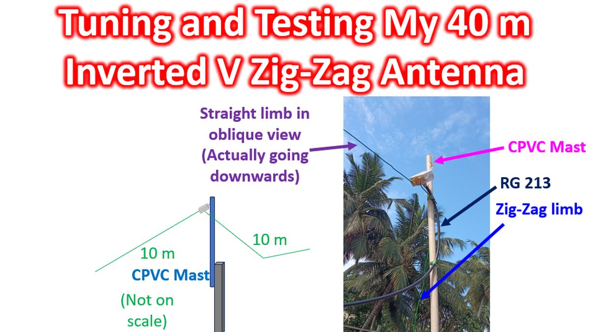
One limb of the inverted V goes straight down and the lower end is about 2 m from the ground, tied to a metallic pole with a nylon string. Spacing from the metallic frame of the compound fence will be about 1 foot. Other limb goes down in one direction first and then in another direction, both being tied to the metallic frame of the fence using nylon string. Coconut trees seen in the picture are actually in a compound across the road and not anywhere near the antenna, though it appears like that in the oblique view. If they were, I could have tied my antenna high up easily, as I used to do at my parent’s home about 4 decades back!
I had bought 30 m of RG 213 coaxial cable, with PL 259 connectors pre-crimped on either side, for convenience, as I am not good at crimping PL 259 connectors. Actually I do not need 30 m, but that was the only length with pre-crimped connectors available at the dealer. There are about 23 turns of surplus RG 213 coaxial cable, with a turn diameter of about 20 cm, kept inside the shack.
I wonder whether it will act as a line isolator or choke off all the RF output of my radio. In the former case it will be beneficial while in the latter case it will reduce the effectiveness of my amateur communication! I have not calculated the inductance of this coil and I am not sure about its effect on the antenna system for an inverted V zig-zag antenna. Though I have EZNEC Pro+ 7 Antenna modeling software installed in my laptop, I am yet to learn how to use it.
Initially when I tested the SWR of the antenna, it came as around 10:1 with the ‘High SWR‘ warning light coming up in the radio. Immediately I brought down the antenna and checked the junction box. To my dismay, I found that the soldered joint of the central conductor on SO 239 had given way, possibly because the solder which I had used was pretty old and I did not have soldering flux. That was why I immediately bought my new soldering kit by same day online delivery, which I got for 250 INR, around $3! Resoldered the joint as best as possible and remounted the antenna for further testing. Of course I had to use my old 65 W soldering iron as the one in the kit was low power and not suitable for soldering SO 239 connector.
Initial SWR on remounting, was around 3:1 at the lower end of the 40 m band and around 5:1 at the upper end. I had put extra wire length as a loop at both ends for attaching nylon wires. First I trimmed off about 26 cm of those from either ends and the SWR came down to 2.5:1 on the lower end of the band and 3:1 at the upper end. Next I removed another 10 cm from both ends and got SWR to 2.25:1 at lower end and 3:1 at upper end.
Removing one more set of 10 cm each brought it down to 1.6:1 near the lower end of the band and 2.5:1 at the upper end of the band. Here you can see the pieces of wires spliced off in the ‘tuning process”! At this level, I checked SWR on 21 MHz band as well, the third harmonic of 7 MHz on which a 40 m antenna can resonate. It was 1.8:1 at the lower end of the amateur band and 2.7:1 at the upper end.
Though there is a built in SWR meter and a limited automatic antenna tuning facility in my radio, I am using my Cross Needle SWR meter for checking the testing phase, as I am more familiar with it. I have used a short length of HLF 200 cable which is supposed to be an LMR 200 clone, for connecting the SWR meter to the radio. Patch cable has PL 259 connectors at both ends. One end is connected to the radio and other end to the SWR meter. End of the RG 213 coax inside the shack is connected to the SWR meter for testing.
Changed the orientation of the zig-zag limb of the inverted V to avoid some interference to the courtyard and tested once again. This time I was happy to get SWR of 1.2:1 at the lower end of the band and 2:1 at the upper end of the 40 m band. I could hear net control of Charminar Net loud and clear. Most of the other stations were also coming in very well. Finally I could also check in, to the net, with this very compromised mounting of a half wave dipole antenna. I know that my work is not over. Making the connections and mounting secure is another job.
Rechecked on 21 MHz as well and the SWR was unchanged at the lower end of the band at 1.8:1 while it had come down from 2.7:1 to 2.25:1 at the upper end of the band. I am yet to try that band for RX and TX as I am not familiar with band opening times. I have to continue my efforts to bring down the SWR more on higher part of both bands so that I can drive full 100 W from the radio. Still I will not reach the legal maximum of 400 W for my class of license because I do not have a linear amplifier nor do I intend to purchase one!