Working Principle of EFHW Amateur Radio Antenna
Working Principle of EFHW Amateur Radio Antenna
EFHW or End Fed Half Wave Antenna is quite popular among radio amateurs for multi-band portable operatios. While a center fed half wave dipole antenna resonates at its odd multiples, EFHW works well at both odd and even multiples of the basic frequency, which makes it suitable for most of the amateur bands. For example, if basic frequency is 3.5 MHz, it will work well for 7 MHz, 14 MHz, 21 MHz and 28 MHz, all popular amateur radio bands.
Unlike the center fed half wave dipole, EFHW feed point is at a high voltage point of the radiating element instead of at the high current point. Hence it has a high feed point impedance of around 5000 Ohms unlike the 72 Ohms of the centre-fed half wave dipole which matches easily with a 50 Ohms coaxial cable. This necessitates the use of a matching transformer for EFHW.
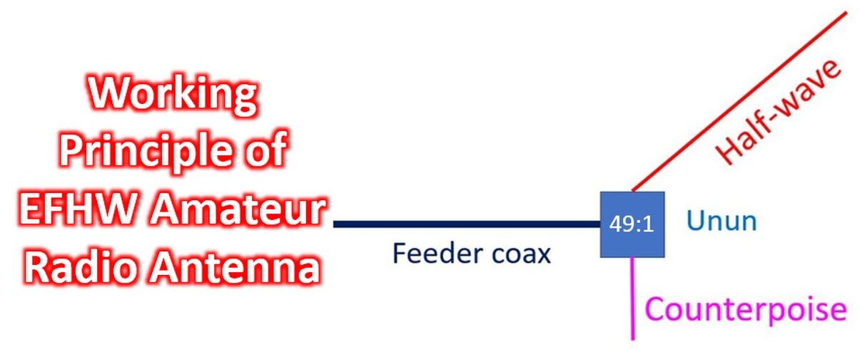
The matching transformer for EFHW is called ‘unun’ as it matches an unbalanced antenna to an unbalanced feed line. Coaxial cable is an unbalanced feedline as RF current flows both on the inner and outer aspects of the shield, making it in effect a three conductor feedline, unlike a balanced feedline like a ladder line.
Detailed and well illustrated instructions for homebrewing a 49:1 unun which is used most often with an EFHW can be found at the blog of KM1NDY. Basic components required are two FT240-43 ferrite cores, 14 gauge enameled wire and one 100pF 15kVDC ceramic capacitor. 4 x 4 x 2 electrical junction box is used for housing the unit and an SO 239 mounted on the box for cable connection.
In case of EFHW, unlike the center fed half wave dipole antenna, the feeder coax is also part of the antenna system and radiates RF energy. You will not like to have this RF brought into your shack as it will cause RF interference in devices as well as give you ‘RF bites’ on touching metallic objects in the shack.
That is why the coax shield needs grounding outside your shack to prevent RF from entering the shack! There is about 10% loss of RF power in the matching transformer and hence the rating will depend on the output power planned. A unun for 1 kW, which is quite legal in some countries, needs to be much bigger and expensive than that for 100 W.
Another related aspect is that if the antenna has to be matched for other bands like 30, 17 or 12 m, it will need an additional external antenna tuner. Built-in automatic antenna tuners available in most modern radios can cater only up to an SWR of 3:1.
Matching these extra bands may require tuners which can cater to SWR over 10:1, while an antenna tuner may not be needed for the regular bands mentioned earlier. Even then, the power loss can be quite significant on those extra bands leading to reduced efficiency. The losses occur in the feeding coax and the matching transformer.
It is also mentioned that due to the high feed point impedance, EFHW is less height dependent than a center fed half wave dipole antenna. This may be useful in situations where you cannot have the antenna high up due to the non-availability of suitable supports. Different types of installations tried in limited spaces are vertical, inverted V, inverted L and zigzag, instead of the horizontal mounting of the typical center fed half wave dipole antenna.
It is needless to say that a non-conducting pole has to be used for a vertical installation. As expected performance and angle of radiation will vary with the type of installation, and so will the SWR. Of course, mounting at maximum possible height will give maximum performance as height is power for antennas! Increasing height will certainly increase the need for better supports as well as lightning protection.