Important Antenna Parameters
Important Antenna Parameters
Important antenna parameters of interest to the amateur radio operator are gain, bandwidth, radiation pattern, beamwidth, polarization, impedance and radiation resistance. In addition there are directivity and front to back ratio for a directional antenna. An easy to measure parameter is the SWR or standing wave ratio.
Each of these parameters assume more importance in certain circumstances. For example, the beamwidth is important in LEO satellite operations. An antenna with a wider beamwidth is easier to point at a fast moving satellite for a beginner, while one with higher gain and directivity, but having narrower beamwidth will be more difficult to point exactly.
An antenna with lower bandwidth will not cover the entire alloted frequencies of a given amateur radio band. For example, some antennas are meant for the CW end of the band while others are meant for the upper SSB part of the band. Bandwidth can be expressed as the range of frequencies at which the SWR is less than 2:1. Using thicker antenna elements is often mentioned as an option to increase the bandwidth.
Gain of the antenna can be expressed either with reference to an isotropic antenna as dBi or with reference to a dipole antenna as dBd. Isotropic antenna is a theoretical antenna with a perfect spherical radiation pattern. Dipole antenna has a directivity along its broad side and hence has a gain of 2.15 dBi with respect to the isotropic antenna. Hence gain expressed as dBd of any antenna will be lower than that expressed as dBi by 2.15. Radiation pattern of a half-wave dipole antenna has a dumb-bell shape.
Polarization of antennas could linear, circular or elliptical. Linear polarization can be further classified into horizontal and vertical. A vertically placed Yagi-Uda antenna has a vertical polarization of the radiated waves while a horizontally placed one has horizontal polarization of the beam. Circular polarization could be right hand circular polarization or left hand circular polarization, depending on the direction in which the beam rotates.
Circular polarization is ideally needed for satellite communication ground station antennas. This is because the satellite spins and tumbles in orbit so that antenna orientation changes continuously, though most satellite antennas are having linear polarization. Circular polarization is achived by having two Yagi-Uda antenas built on the same boom with elements perpendicular to each other and fed by a phasing section of cable. If the phasing and dimensions of elements are not accurate, it will end up as an elliptically polarized antenna instead of a circularly polarized one.
The gain of a Yagi-Uda antenna increases as the number of elements are increased. This will also increase its front to back ratio. An indication of front to back ratio can be obtained by changing the direction of a VHF Yagi-Uda antenna and checking the access to local repeaters. When I tested my seven element Yagi-Uda antenna for VHF, when I turned the antenna South, in the direction of VU2MJJ repeater, access to VU2EDJ repeater in the North was completely lost. My vertical omnidirectional antenna gives access to both repeaters.
Beamwidth of the antenna is reduced as the number of elements increase. This will make pointing the antenna in the direction of a moving satellite more difficult. Hence it is often mentioned that a beginner in LEO satellite operations start with an antenna having lower number of elements and obviously with a lower gain as well. Automated control of antenna with rotator and control software is useful in achieving good tracking and high gain with multi-element Cross-Yagi with circular polarization, one of the best for low earth orbit satellite operations.
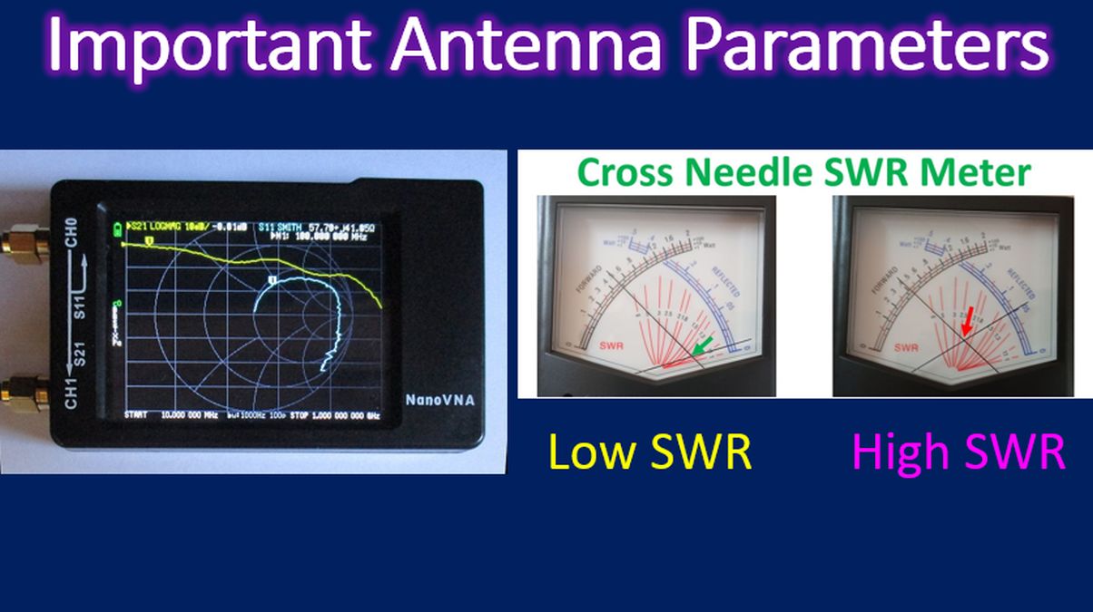
Characteristic impedance of the antenna should match that of the transmission line and radio. Otherwise matching systems are needed for good radiation of signals. A half wave dipole antenna has an impedance of around 70 Ohms while the folded dipole antenna has an impedance of around 280 Ohms. Thus different types of antennas have different impedance. In Yagi-Uda antenna, adding parasitic elements changes the impedance of the antenna. Impedance of an antenna and many of the other antenna parameters can be measured using a vector network analyser, known in short as VNA.
Another important parameter of an antenna is its resonant frequency. Resonant frequency can also be determined using a nanoVNA, which is a relatively cheap and affordable equipment for the amateur radio operator compared to conventional network analyzers which are large and costly. Resonant frequency will depend mainly on the length of the driven element in relation to the wavelength. It will also depend on the speed of electromagnetic waves in the material used.
SWR, though easy to measure, is not the ultimate in antenna measurement. For example, a dummy load may have an ideal SWR of 1:1, but will not radiate any power as radiofrequency and all the power fed to it is converted to heat and lost. The part of the impedance of the antenna contributed by the radiated power is known as the radiation resistance. Another term in this context is the antenna efficiency. A highly efficient antenna radiates most of the power fed to it as radiofrequency and less is lost as heat in the antenna system.