Adding Balun and Tuning 10 m Dipole
I had made a half-wave dipole antenna for 10 m recently, but had not added a 1:1 balun at the feedpoint. There was no PL 259 connector at the cut end of RG 213 for connection to my recently purchased 1:1 balun. Yesterday I crimped a PL 259 connector to the cut end of the RG 213 which was 15 m long. Now it was ready for connecting the 1:1 balun.
This was the existing 10 m half-wave dipole antenna which was brought down for enhancement. You can see the 3 m long CPVC pipe used for mounting along with a short length of PVC pipe on which the cut end of RG 213 and antenna elements were fixed.
This video clip was taken after the PL 259 connector had been crimped at the cut end of RG 213. When I checked the lengths of the insulated copper wires which formed the radiating elements, I found that one was about 5 cm longer and I trimmed it.
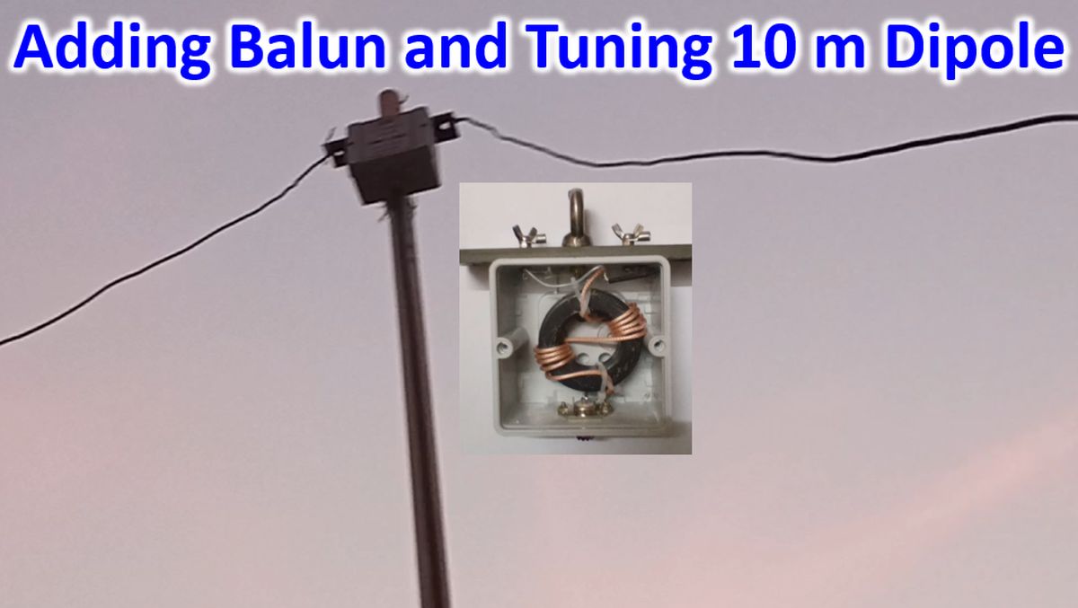
The antenna wires were then fixed on the 1:1 balun on either sides. The stainless steel hook for fixing the balun to the mast can be seen in the center. Antenna elements were secured with nylon ropes as an added option to prevent stress on the connectors.
PL 259 connector at the end of RG 213 coax was then carefully inserted into the SO 239 connector on the balun. To prevent splaying of the inner conductor of SO 239, extra solder at the tip of PL 259 had been scraped away prior to that. It was ensured that the spokes on PL 259 were correctly fitting into the notches on SO 239.
Outermost part of PL 259 was then threaded over the SO 239 connector to have a secure fix.
The hook on the 1:1 balun was tied to the end of 3 m long CPVC pipe and mounted on the parapet of the balcony so that the total height above the terrace would be around 4 m and height from the ground about 7 m. Both ends of the radiating elements were tied to nearby supports on the terrace itself with nylon ropes so that it formed an inverted V 10 m antenna.
The initial VSWR was 3.5:1 at the lower end of the 28 MHz band and 5:1 at 29 MHz. Then I folded and twisted back 15 cm of the radiating elements on both sides. Revised SWR was 1.1:1 at the lower end and 2.3:1 at 29 MHz. As I wished to optimise for the usual region in which I have worked SSB stations earlier, I reduced the length of elements by another 5 cm. Then VSWR became 2.0 at the lower end of the band and 1.8:1 at 29 MHz. VSWR of 1.1:1 was obtained for the range between 28.4 MHz to 28.6 MHz, which was what I was looking for.