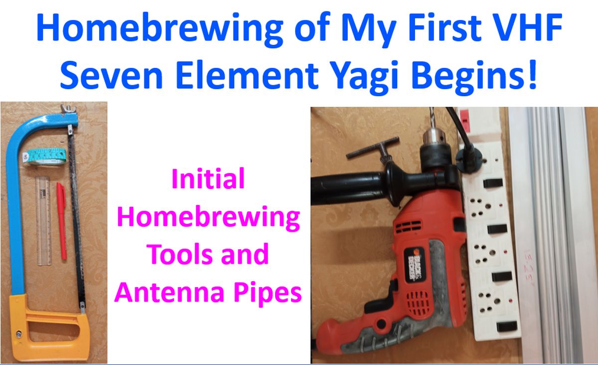
Homebrewing of My First VHF Seven Element Yagi Begins!
Homebrewing of My First VHF Seven Element Yagi Begins!
I have not homebrewed any antenna for the past 35 years. Beyond that, I had first made an inverted V for 40 meters for my homebrew solid state VU2VWN QRP. I was using 75 Ohms TV cable for connecting the antenna to the QRP as I did not know about 50 Ohms cable at that time. BD 139 finals of the QRP would go QRT often and I had no way of checking the SWR. Later I moved on to homebrew 3 x 807 QRO which was a hybrid circuit using the solid state VFO of the QRP. For that I had made 40 m and 80 m horizontal dipole antennas. I could also make an SWR bridge and check the SWR with my analog multimeter and found it reasonable. None of my vacuum tubes went QRT and I could comfortably work DX, though mostly on CW, including some contacts from the US.
Now I have come back to Ham Radio after a break of almost 10 years, initially on VHF using a magnetic mount quarter wave antenna and later with my CP22E antenna at about 9 m from the ground using a 10 m HLF 200 cable. Had also a few tests on UHF using the CP22E antenna with low power in view of 2.25:1 SWR. Homebrewing skills have almost disappeared and it is only because of constant motivation by my 5 year old grandson that I am venturing into it once again! Read about several multi-element Yagi designs over the past few months and talked to several Ham friends over phone and VHF. My main concerns were the lack of availability of the needed hydraulic clamps and baluns with most designs. Finally I have zeroed in on the KA0NAN seven element yagi which had been redesigned by VU3NSH. Still there was a bottle neck, it needed a Gamma match, which I was not familiar with.
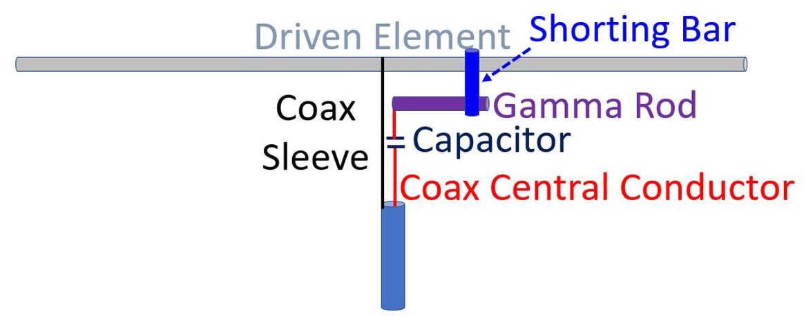
So read a bit about the Gamma match. In case of a Yagi-Uda type of antenna, it allows the driven element to be a single rod or tube without being cut at the feedpoint, giving more physical integrity to the system. As the RF voltage at the centre of a half wave antenna is zero, the outer sleeve of the coax can be connected here, which corresponds to the position on the boom as well. The central conductor of the coax is then connected beyond the centre point through a capacitor to tune out the inductance of connecting arm of antenna. In the KA0NAN/VU3NSH design, the capacitance is provided by a piece of coaxial cable with jacket removed and inserted into 7.25″ aluminium tubing of 3/8″ diameter. The tubing has to be slided in and out to find the find lowest SWR while transmitting at low power and later confirmed on high power, before fixing the screw on the shorting bar.
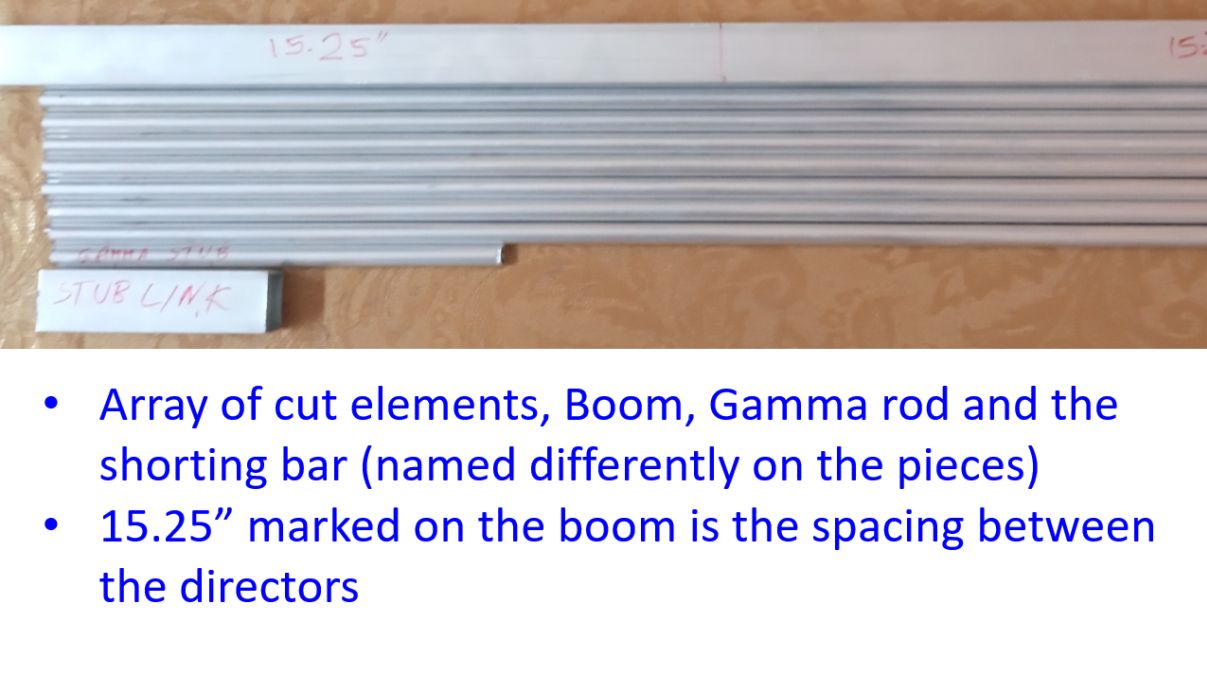
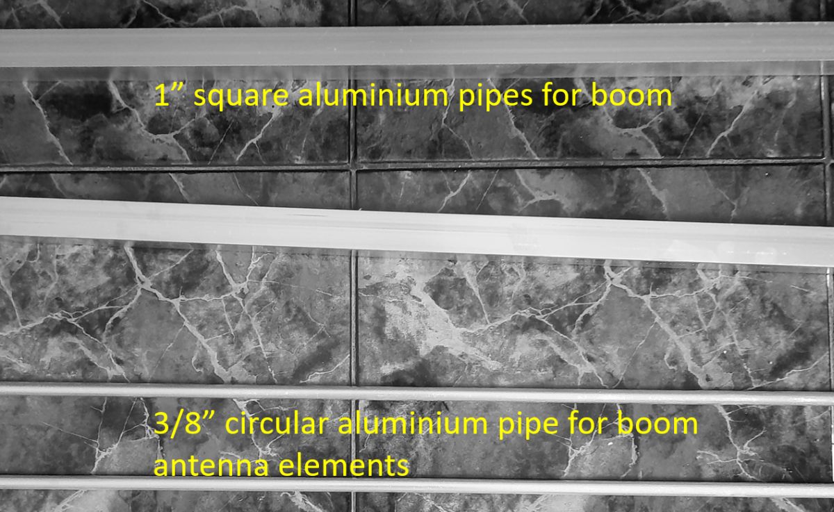
I have bought 3/8″ round aluminium pipes for the elements of the antenna and 1″ square aluminium pipe for the antenna boom, which are available at a very low cost locally, thanks to the flourishing aluminium fabrication industry over here. I had procured a spare HLF 200 cable of 10 m length precrimped with PL 259 connectors on both ends, as well as an SO239 connector and a patch cable for SWR checks, both bought online. Of course, a cross needle SWR meter was also bought online for this purpose earlier.
Next I checked the inventory of tools which I already have with me and found that it is almost enough to start with. I had a collection of drill bits along with an electrically driven drill, extension board, hacksaw, red marker pen, measuring tape and a small transparent scale, as seen in the initial picture. Initially I marked out the positions where I have to drill holes on the boom for the various elements, using the measuring tape and marker pen. Next I marked the places where the 3/8″ pipe has to be cut to form the antenna elements. Then they were cut using the hacksaw. The boom was also cut with about three inches extra on the reflector side and two inches extra on the director side. A solid alumninum piece was needed as the shorting stub, which I did not get from the local stub. Planning to try a piece of the 1″ square pipe as the shorting stub. The gap between the Gamma match and the driven element is given as 1.5″. So I have cut 3.5″ shorting bar of the 1″ square pipe. Length of the 3/8″ aluminium pipe has been mentioned as 7.25″, that was also cut. Next I have to drill holes in the boom for the 3/8″ pipes which I am planning to do on another day.