Factors Affecting VSWR
Usually standing waves occur in the transmission line when there is impedance mismatch between the transmission line and the antenna. Standing wave ratio or SWR is the ratio between the maximum and minimum amplitudes of the standing wave. When there is an impedance mismatch, part of the signal is reflected back to the transmitter from the antenna. This reduces the effective power transmitted and thereby the efficiency. SWR is usually measured either by an external SWR meter or a built-in SWR meter in the radio. Usually it is the voltage SWR that is measured using an SWR meter and is known as VSWR. Highest level of VSWR occurs when the antenna is not connected (open circuit) or when there is short circuit in the transmission line. Modern software defined radios usually indicate this by a red HIGH SWR indicator and shut down the power output of the radio to prevent damage to the final RF power amplifier.

One of the reasons for getting a very high VSWR reading is an improperly connected antenna connector. By repeated connection and disconnection, inner connector of SO 239 connectors can splay out causing improper connection with open circuit. This causes a HIGH SWR indicator to light up as soon as the PTT is pressed. Using a nose plier to shape the inner connector of the SO 239 is useful to rectify this problem. PL 259 connector of the antenna should be carefully fixed so as to avoid an open circuit and one of the simplest causes for HIGH SWR which I have noted sometimes. I am not sure whether this is due to the poor quality of the SO 239 connector on the SWR meter or due to my faulty method of connecting it!

Another cause of HIGH SWR due to open circuit is disconnection of the soldered joint of one of the conductors at the antenna feedpoint. This can occur after antenna manipulations or even after a storm with high winds if the feedpoint is not well protected as often occurs in a hasty installation of a homebrew dipole antenna. It can be identified by inspecting the feedpoint and corrected by proper resoldering. Sometimes the contact may be poor due to dry solder which may need checking by a multimeter to sort out. These are simple things which I have encountered in my homebrewing ventures, not professional advice from those who use an antenna analyzer which I am yet to acquire. If there is a difference between the characteristic impedance of the transmission line and the antenna, part of the output of the radio is reflected back from the antenna due to the mismatch producing a standing wave.
In a simple example noted in an ARRL article by K5DVW, if the antenna impedance is 100 Ohms and transmission line impedance is 50 Ohms as in most of the coaxial cables used for amateur radio, this will produce a VSWR of 2:1 with 33% of the voltage wave and 11% of the power being reflected back. Obviously, we cannot do anything about the characteristic impedance of the cable as it depends on the physical construction. Factors which influence the characteristic impedance are the conductor size, spacing between the conductors and material used for insulation between them. Antenna impedance can be changed if you have homebrewed it, by trimming or lengthening it for the indented frequency.
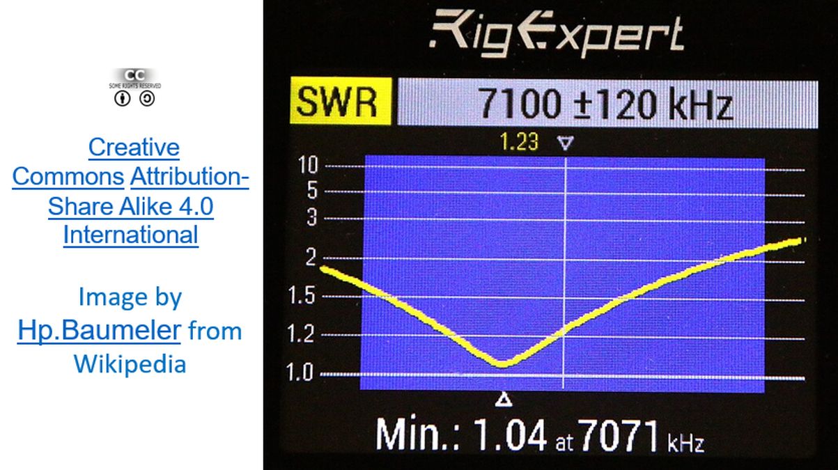
Resonant frequency of the antenna can be found using an antenna analyzer. An expensive one being used by some of the antenna designers, even in my region is RigExpert. I could see a nice picture of an SWR graph using it, on Wikipedia, by by Hp.Baumeler, which is being reproduced here as it is licensed under the Creative Commons Attribution-Share Alike 4.0 International license. The picture shows SWR as a function of frequency. A cheaper NanoVNA can also be used as an antenna analyzer, which is on my wish list for the next purchase! As you can easily appreciate from the graph, a non-resonant antenna will present a higher VSWR. That is why we usually tune antennas by trimming or lengthening the radiating element to have resonance at the centre of the band. More factors like distance between elements also come into place in case of multi-element antennas like Yagi-Uda antenna. Other confounding factors are conducting material in the vicinity of the antenna, distance from ground etc.
An important limitation while measuring VSWR is that ideally the SWR meter has to be closest to the antenna. The loss in the transmission line attenuates the reflected wave and hence the SWR. SWR measured near the antenna will be higher than that measured near the radio! More attenuation in the cable would mean a falsely low VSWR measurement near the radio, suggesting better matching of the antenna system. It is more important to measure VSWR at the antenna end if the cable run is long. Longer cable would mean more of cable loss and higher chance of falsely low SWR being noted near the radio. I have tried to summarize a bit of my practical experience while homebrewing antennas and some theoretical aspects noted by reading online. It is far from complete and I am continuing to learn and hope to post updates or corrections if needed, later on.