Modified Inverted V 40 m Antenna
Modified Inverted V 40 m Antenna
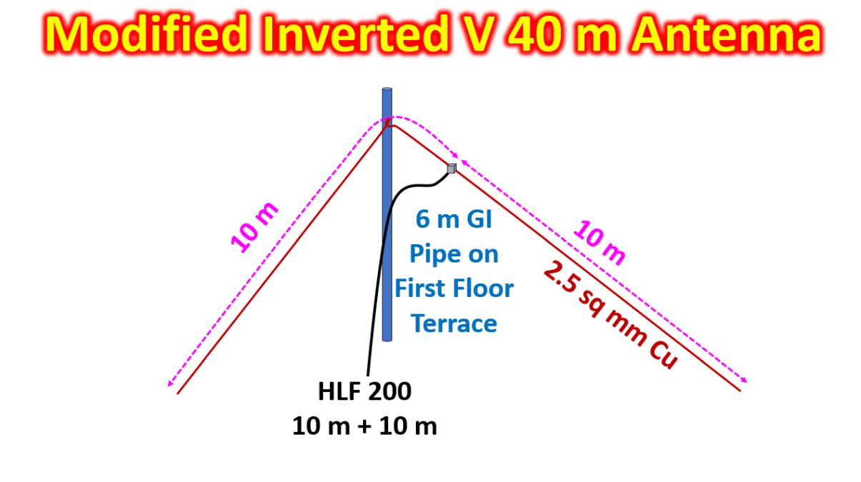
I had mounted my Inverted V 40 m Zig-Zag Antenna on a 3 m long CPVC hotwater pipe kept on the fence of first floor terrace. Ten meters of HLF 200 coaxial cable with PL 259 connectors at both ends was used to connect the feedpoint to the radio. As per advice given by fellow hams, I tried to raise the antenna a bit. As the 3/4 inch CPVC pipes were not strong enough to be extended to 6 m, I decided to use a surplus GI pipe which I had, of 6 m length. There was a pre-drilled hole at about 2 feet from one end. I used it thread nylon wire and shape it as a sling on which I could pull up the antenna.
Fixed the GI pipe on the first floor fence with five nylon string ties so that it was fairly stable in the vertical position. Position in which the mast could be tied on the fence securely was not corresponding to the feedpoint of the antenna. So it turned out to be a modified inverted V as shown in the initial sketch, which is not according to scale. Previous configuration is shown here for comparison. Please note that this is not an optimal antenna configuration, only a method of suiting to my space constraints. After all, amateur radio is for experimentation and innovation! I am sure that there are many more city dwelling radio amateurs out there, with space constraints like me or even more. This post is also intended to motivate them to try out whatever configuration is feasible in their setup.
Used an SO 239 barrel connector to join another piece of HLF 200 cable with pre-crimped PL 259 connectors at both ends. This time I did not keep the surplus HLF 200 cable as a coil in the shack. Instead I made a large loop and fixed it on the terrace at about 5 feet height using nylon wire ties. This is in an attempt to prevent a coil of cable from acting as an additional inductor in the circuit and possibly acting like an electrically shortened loaded coil dipole. Checked the SWR of the new configuration and found that it has changed from the previous configuration, as expected. SWR was 1.4:1 at the lower end of the band and 1.7:1 at the middle of the band while it was 2.5:1 at the upper end. Did not go for any further trimming or lengthening of the antenna wire for time being, as I was a bit tired after doing all the job single handedly. I could check in to the VWN Vasanth net on 7050 kHz and Charminar net on 7080 kHz comfortably.
After that I could also have comfortable contacts with stations at Shimoga, 430 km and Belgaum, 530 km. Further refinements planned for next day if possible to improve these personal distance records. I know very well that this is not the maximum distance possible with my HF radio on 40 m SSB. I am driving only 70% of the maximum RF power. Actual power delivered is much lower. May be I will try coiling the surplus HLF 200 cable and check whether it will shift the point of minimum SWR as I had noted in my previous configuration with 30 m of RG 213 cable. I had kept about 15 m of the surplus cable as a coil with 23 turns of about 20 cm diameter, inside my shack. This time I might keep a smaller coil on the terrace to see whether it will act like a common mode choke, as I do not have a balun at the feedpoint, to match the ‘balanced’ dipole antenna to the unbalanced coaxial cable feedline.