What are catenary wires?
A catenary wire (also known as a messenger wire) is the upper structural cable in an overhead railway electrification system that supports the lower power-delivering contact wire so it stays at a uniform height above the tracks. In broader engineering and everyday railway usage, “catenary” also refers to the entire overhead wire assembly that supplies electricity to trains, trams, and trolleybuses.
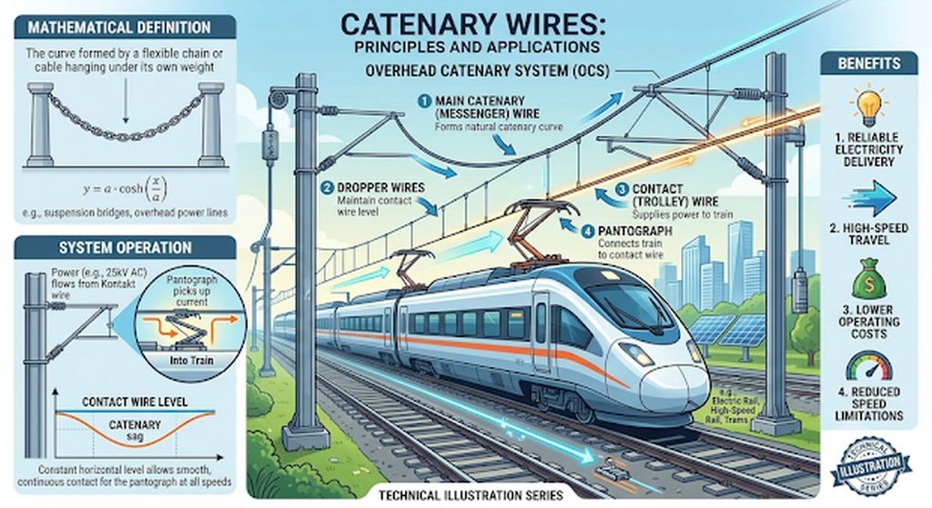
Why Catenary Systems Are Needed
Any flexible wire strung between two poles naturally sags in the middle under its own weight. On slow urban streetcars, a single overhead wire is often sufficient. On mainline and high-speed railways, however, a single sagging wire creates major problems:
- Pantograph Bounce & Arcing: As a train speeds along, its roof-mounted collector arm (the pantograph) would be forced up and down at every support pole, losing contact at mid-span and causing destructive electrical arcing.
- Mechanical Wave Damage: A moving pantograph sends a mechanical ripple along the wire. If the train travels faster than that ripple, standing waves build up and can snap the conductor.
Engineers solve this by suspending a straight, level
contact wire beneath a curved
catenary wire using vertical hangers of varying lengths, keeping the power pickup surface flat across long spans.
Key Components of an Overhead Catenary System
- Catenary (Messenger) Wire: The upper stranded conductor engineered for high tensile strength. It hangs in a natural curve between trackside masts, bears the mechanical weight of the assembly, and carries electrical current in parallel with the contact wire.
- Contact Wire: The lower wire that makes direct sliding contact with the train’s pantograph. Made from hard-drawn solid copper or wear-resistant copper alloys (such as copper-tin, copper-silver, or copper-magnesium), it features longitudinal grooves along its sides so support clips can grip it from above without obstructing the smooth underside.
- Droppers (Hangers): Vertical wires clipped between the upper catenary wire and the lower contact wire. They are longest near the support poles and shortest at mid-span, holding the contact wire parallel to the rails.
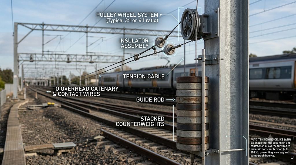
- Auto-Tensioning Devices (ATDs): Counterweight pulleys, springs, or hydraulic tensioners at the ends of wire sections that maintain constant mechanical tension (typically 9 to 20 kN) despite thermal expansion in hot weather or contraction in the cold. High tension raises the mechanical wave speed in the wire well above the train’s top speed.
- Cantilevers & Stagger: Insulated support arms attached to trackside masts. They position the contact wire in a gentle horizontal zig-zag pattern (“stagger,” typically ± 200 mm on straight track) so the wire sweeps across the pantograph’s carbon collector strip rather than wearing a single groove into one spot.
The Physics and Mathematics Behind the Name
The term
catenary derives from the Latin word
catena (“chain”) and describes the exact geometric curve formed by any uniform, flexible cable hanging freely under gravity between two supports.Mathematically, a catenary curve is defined by the hyperbolic cosine function:
y = a cosh (x/a)where a represents the ratio of horizontal tension to the cable’s weight per unit length. Beyond electrified railways (such as Indian Railways’ 25 kV AC overhead equipment), this same catenary geometry governs high-voltage power transmission lines, suspension bridge main cables, and marine mooring lines.
Related Posts


About The Author
