Half Wave Dipole Antenna
Half Wave Dipole Antenna
Here is the transcript of the video shown above: Half wave dipole antenna requires two supports, at either ends, one is here, and another is here. And central point also will need some support, otherwise it will sag, especially when you are using a balun here, which have some weight. So you will need a support here also. Why is this balun used? Half wave dipole antenna is a balanced antenna, while the coax feeder is an unbalanced line. So you need a balancing between, that is known as balun, connected in between.
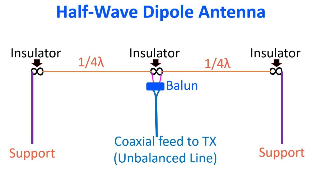
Each halves of the half wave dipole antenna, will be quarter wavelength. And you need insultors wherever it is being connected to other structures. The wire itself can be copper wire with insulation or without insulation and you can also use multi-stranded wires, instead of a single stranded wire. The maximum voltage in a half wave dipole antenna is at its ends, both ends have maximum voltage, while the maximum current is at the centre.
So radiation of the signal, electromagnetic signal, is mostly towards the centre, for the half wave dipole antenna. At the same time, as the maximum RF voltage is at the ends, one, it has to be insulated, and care has to taken that nobody is likely to touch these ends. But when it is mounted horizontally, it is very unlikely, because it will be at a height with the masts. But, half wave dipole antennas can also be mounted vertically, though it is not very practical for higher wavelengths, that is the lower frequencies, length will be too difficult to mount it vertically.
If you mount it vertically, the advantage is that the antenna will be omnidirectional. So if you are mounting it vertically, this one portion will be lower down, and chance for somebody touching is there. Of course, if the material is insulated, that risk is not there.
This is the radiation pattern from the half wave dipole antenna which has been mounted horizontally. You can see that the voltage maxima shifts from either ends. First it will become positive on one side and next it will be positive on the other side. That is because it is an alternating RF current. An animation, public domain image from Wikipedia. The electric field is radiating perpendicular to the horizontal element. So that is why I said, if this horizontal element, instead of being horizontal, if it is kept vertical, this electrical field will radiate all around, omnidirectional.
But in a horizontal position, it will be perpendicular to the direction of the antenna elements, if the antenna elements are like this, electrical field will be perpendicular. That is why, compared to an isotropic antenna, an antenna which radiates spherically in all directions, dipole antenna has some gain. That is usually mentioned as 2.15 dBi, that is the gain for a dipole antenna, because it radiates perpendicular to the position of the antenna. So, towards the end of the antenna, in this direction, there is hardly any radiation. That is the null for the antenna. For reception also, signals in this direction will be maximum received, while signals perpendicular to the direction, that is along the direction of the ends of the antenna, reception also will be poor. So dipole antenna has some directivity, especially in the horizontal position.
Now, moving on to calculation of length of the antenna, that is when you want a 40 m amateur band antenna, you consider the frequency as 7 MHz. Or if you want central band, you can consider as 7.1 MHz, because 7 to 7.2 is the band in India. So the length in the meters of the antenna will be, 150 into A, divided by frequency in MHz. ‘A’ is the correction factor for end effects. Typically it is around 0.95. So what you have to do is, it will be difficult to lengthen an antenna, so cut slightly longer than what you get by this measurement. And even though it is called half wave dipole, the length is usually a little shorter because of the end effects.
Now what is this end effect? Antenna calculations are done for free space, according to the formula. Then, when you have antenna in air, and surrounding structures are there, these can effectively lengthen the antenna by decreasing inductance and increasing capacitance of the antenna. Then it is affected by the length to thickness ratio of the material used for the antenna, that is wire we are using. Supporting insulators, feed system, surrounding objects like earth, buildings and trees, all these affect the length of the antenna. So that is why, a correction factor, which has been given as ‘A’, is mentioned in the formula.
Now, how is this tuning of the antenna done? Once you have put up the antenna, you can check the SWR and adjust the length of the antenna, by trimming slightly on either side equally to get a match of the SWR, ideally 1:1, but at least below 1.5:1 is acceptable and even a slightly higher 2:1 also can be accepted if you have an antenna tuner. So, as mentioned earlier, it is difficult to lengthen the wire, that is why you measure a little higher length and then trim while you are tuning the antenna.
A half wave dipole antenna can be used at odd multiples, where it will be resonant. But if it is used at even multiples, like a 7 MHz antenna being used at 14 MHz, it will present a high feed point impedance. So it cannot be used. A 7MHz antenna can be easily used at 21 MHz as well. But of course, always it is better to have the correct wavelength measured and then the antenna used for that particular band itself, because some of my friends have reported that when they use it for higher bands, there is some increase in the SWR.
Half wave dipole antenna is probably the most commonly employed antenna and it is part of other antennas like a Yagi-Uda antenna, where other parasitic elements are added. And also, it is there in the central portion of the parabolic reflector antenna.