Atrial pacing with 2:1 AV block – EP tracing
Atrial pacing with 2:1 AV block – EP tracing
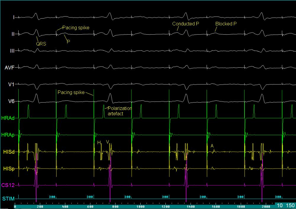
Tracings from an electrophysiological study with intracardiac and surface electrocardiograms showing 2:1 AV conduction during atrial pacing. The upper six channels in white colour are surface electrocardiograms (leads I, II, III, AVF, V1 and V6). The pacing spikes are sharp deflections of very short duration. The P waves and QRS complexes are marked in lead II. The width of P waves and QRS complexes are more than the usual because the recording speed is much higher for an EP study, usually at 100 or 200 mm/s rather than the 25 mm/s for usual ECG tracings.
Higher recording speeds are used to delineate short intracardiac signal intervals well. Only half the paced P waves have an associated QRS complex while half do not have (blocked P). This is because the atrial pacing rate is above the Wenckebach threshold of the AV node. Please note that 2:1 AV block is the highest grade of Wenckebach type of block possible (2:1 conduction can also occur in Mobitz type II AV block).
The polarization artefact is seen in HRAd (High Right Atrium, distal) channel. This suggests that the pacing stimulus is being delivered from this electrode pair. HRAp (HRA proximal) channel does not show this artefact, nor does any other channel. The polarisation artefact is a seen as a broader signal with an amplitude lesser than that of the pacing stimulus, in the channel from which the pacing stimulus is being delivered. This artifact helps us to find the site of pacing when an EP tracing is given.
HISd (distal His bundle electrode pair) shows a good triphasic His bundle potential (H) and ventricular signal which is of lower amplitude than in the CS12 (distal pair of coronary sinus electrodes). The CS12 channel in this case shows a small pacing signal and a high amplitude ventricular signal. The electrodes in the coronary sinus are usually numbered from distal to proximal (CS12 to CS9-10 in case of decapolar electrode). The STIM channel just depicts the intervals at which the pacing stimuli are delivered, without recording any intracardiac signals. There is also a marker at the level of the pacing stimulus.
The various intervals (PA, AH, HV, RR, PP etc) can be measured with online calipers. Some of the channels have been hidden in this image (CS34 – CS9-10) to prevent cluttering of the screen. This helps the operator to concentrate on the tracing important for this particular study. In case of need, they can always be made available on the screen. It is possible to change the recording speed of the display in online as well as offline mode. This helps in evaluating the rhythm better.
Please note that the conducted P waves have a corresponding A wave, followed by H and V in the HISd channel, while the blocked P waves have only an A and no H or V. This indicates that the A is blocked above the His bundle, presumably at the AV node. The A wave in the HRAp channel precedes that in the HIS channels indicating supero-inferior conduction. The intervals in the lowermost green bar is cumulative time interval from 0 to 2000 ms.
Related Posts

About The Author
Johnson Francis
Former Professor of Cardiology, Calicut Govt. Medical Kozhikode, Kerala, India. Editor-in-Chief, BMH Medical Journal