Unipolar VVI Pacing
Unipolar VVI Pacing
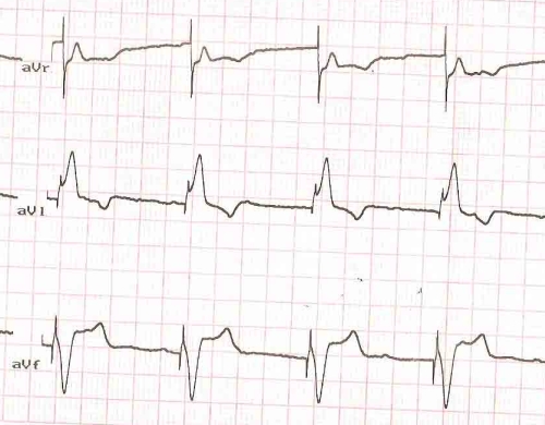
Unipolar VVI Pacing: Leads aVR, aVL, aVF
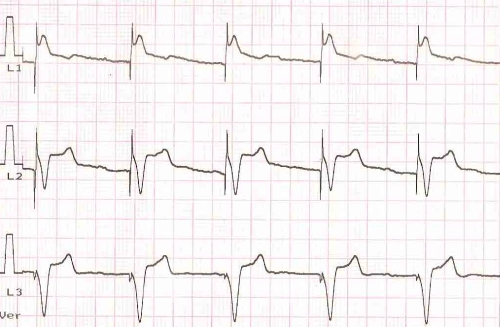
The sharp vertical deflection preceding each QRS complex is the pacing spike or artefact. The ECG shows a large amplitude pacing spike indicating that the pacing mode is unipolar. In unipolar mode, the electrode at the tip of the pacing lead acts as the cathode and the pacemaker can as the anode. Cathodal pacing has better threshold than anodal pacing. That is why the lead tip is programmed as cathode. In bipolar pacing, the lead tip still acts as the cathode while a proximal ring electrode acts as the anode. In that situation, as the current circuit is completed within the ventricle itself, the spillover to the surface ECG recording electrode is small so that pacing spikes are quite small and hardly visible in some leads.
Transvenous temporary pacing is always bipolar as the pacemaker is not implanted within the body and hence cannot act as an anode. Permanent pacing can be programmed in unipolar or bipolar modes. Similarly the sensing of the lead can also be programmed either unipolar or bipolar. Unipolar pacing can sometimes cause local pacing in the region of the pacemaker can. This is more likely if the active side of the can is kept in contact with the pectoral muscle. Usually the pacemaker is placed within the pocket in such a way that the active side faces the posterior aspect of the skin. This will decrease the chance of local pacing in case programming in unipolar mode is required.
Even though this ECG is from a person implanted with a VVI pacemaker, it is not possible to make out that from this ECG as all the QRS complexes are paced complexes. Demand function can be identified only when there are spontaneous QRS complexes, in which case the pacemaker will wait for the programmed interval before giving out the pacing spike once it senses a QRS complex. If the sensing is defective, the pacemaker will function as a fixed rate pacemaker ignoring spontaneous QRS complexes. That mode will be termed VOO mode.
Spontaneous P waves and AV dissociation are evident on close scrutiny of the ECG, especially in aVF. Lead I shows an LBBB type pattern due to the right ventricular location of the pacing lead. Inferior leads show negative QRS complexes, indicating an activation proceeding from below upwards, suggesting the location of the lead tip in the right ventricular apex. The axis will be downward in outflow pacing. Left ventricular pacing will give a right bundle branch block pattern. Pacing of the septal aspect of the right ventricular outflow tract is being used by some as a possible way of more physiological pacing in terms of activation sequence of the two ventricles, mimicking the natural sequence.
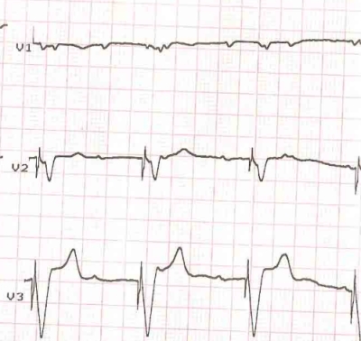
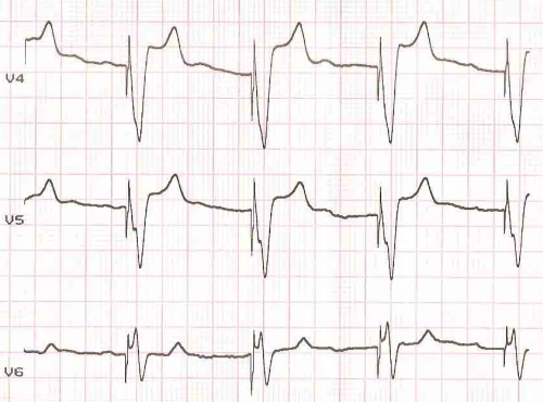
Though we would expect a dominant positive QRS in V5, V6 in a left bundle branch block pattern with right ventricular pacing, when the pacing is done from the right ventricular apex, V5 , V6 shows a predominantly negative QRS complex as the activation proceeds away from the apical region. This is evident in the tracing shown. The rS pattern in V6 is likely to be thought of as an RBBB pattern and hence indicating left ventricular pacing. But lead I shows the LBBB like pattern of right ventricular pacing and so does V1, showing a negative QRS, though of smaller amplitude in this case.
Related Posts


About The Author
Johnson Francis
Former Professor of Cardiology, Calicut Govt. Medical Kozhikode, Kerala, India. Editor-in-Chief, BMH Medical Journal